- Battery voltage range
- 0 to 20.000 V on HTB-2020; 0 to 80.000 V on HTB-2060, at 0.001 V
- Over-current range
- 0 to 10.000 A on HTB-2020; 0 to 20.000 A on HTB-2060, at 0.001 A
- Internal resistance
- 0 to 999.0 mΩ, resolution 0.1 mΩ
- Identification resistance
- 0.1 to 999.9 kΩ, resolution 0.1 kΩ
- Capacity
- 0 to 100.0 AH, resolution 0.1 mAH as printed
- Built-in supply output
- 20 V at 2 A on HTB-2020; 60 V at 5 A on HTB-2060
- Static test time
- 1 to 2 s for all functions
- Capacity test time
- 3 to 4 h at a 1C charge and discharge
- Voltage accuracy
- ±(reading × 0.5% + 3 mV)
- Mains input
- AC 85 to 265 V, 50 or 60 Hz, 2 A
A finished battery is judged on more than its voltage. The open-circuit reading tells you the state of charge; the internal resistance tells you whether the cell will deliver current; the capacity tells you what it will deliver over time. A tester that reads all three at one connection is the difference between sampling a batch and screening it.
Product overview
The series is two models over one body shape. They differ in measurement range and in the output capability of the supply built into them: the smaller measures to 20 V and 10 A with a 20 V, 2 A supply, the larger to 80 V and 20 A with a 60 V, 5 A supply.
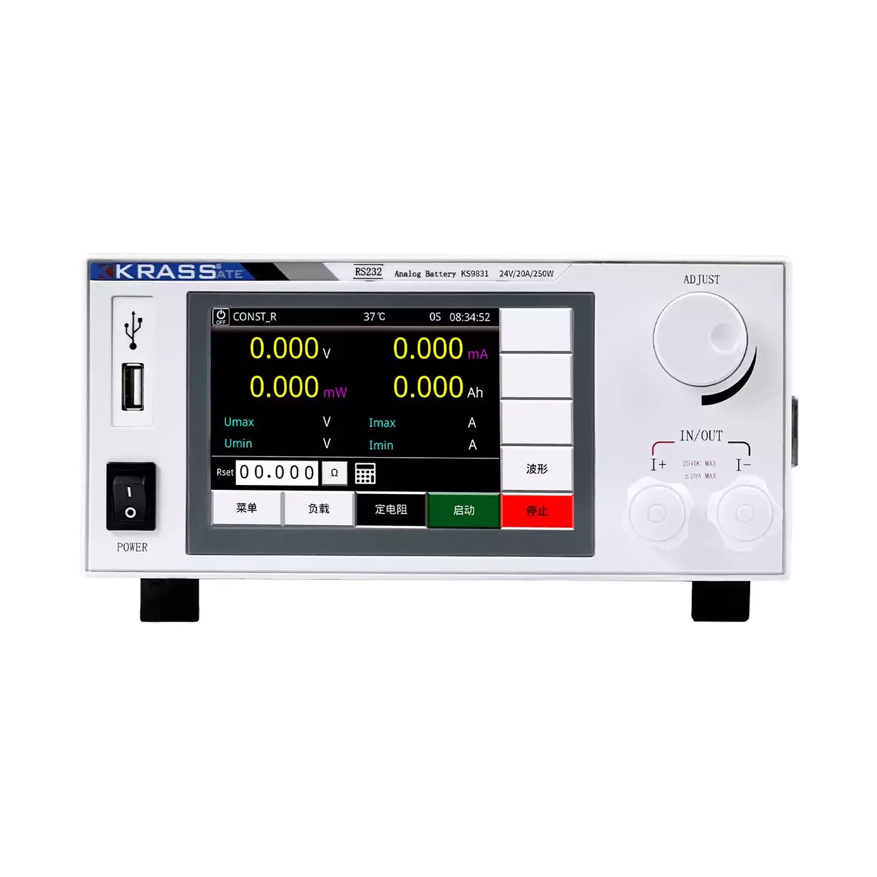
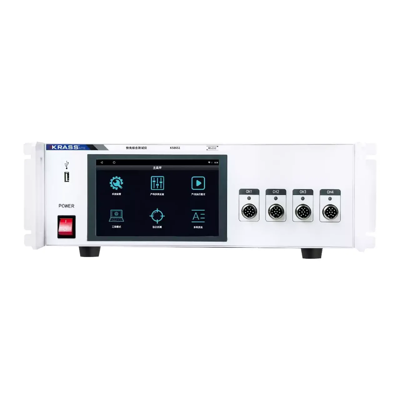
Both connect to the battery on four terminals. The front panel carries the display, the keypad, the language switch, the USB socket and the terminal set, and the rear carries a second terminal set, the cooling fan, the fused mains inlet and the switch.
How the battery tester works
The four-terminal connection separates the current path from the sense path. Current is delivered through the P terminals, while the R terminals measure at the cell, so the resistance of the leads and the contact is not added to the cell’s own resistance. On a cell whose internal resistance is a few milliohms, that separation is what makes the reading meaningful.
The static test reads voltage, over-current, internal resistance and identification resistance in one pass, in the one to two seconds the material gives. Each parameter is compared with an upper and a lower limit set at the instrument, so a cell outside any of them is rejected without the operator reading a number.
Capacity is a different kind of test. The built-in supply charges and discharges the cell at a 1C current, and the instrument integrates what passes through it over the cycle. That is why the same instrument takes seconds for the static test and hours for the capacity test: one reads the cell as it stands, the other runs it through a cycle.
How to select the right battery tester
The pack voltage decides the model. Anything that reaches above 20 V needs the 80 V version, and a pack that is charged to 60 V needs headroom above its own figure, not a model chosen at the top of its range.
The current decides the rest. The over-current range has to cover the highest current the test will draw, and the built-in supply has to be able to charge the pack at the rate the test plan asks for: 2 A and 5 A are the two figures, and a large pack at 1C may need more than either.
The third question is what the test is for. Screening finished cells for a fault needs the static test and settable limits, and the capacity test is not involved. Grading or verifying a pack needs the capacity test, and the time it takes has to fit the bench’s throughput: three to four hours per cycle is a planning figure, not a delay that can be shortened by the instrument.
Finally, decide how results are kept. Storage to a USB flash drive is standard, and the interface can be set to English, which matters for a line whose operators do not read Chinese. Send the pack voltage, the current and the capacity, and a model can be proposed.
Measurement limitations and selection considerations
The capacity range is printed with a unit mismatch: a range in amp-hours with a resolution in milliamp-hours. The resolution should be taken from the manual rather than read off the table, because the two figures as printed differ by three orders of magnitude and cannot both be right.
The accuracy figures for identification resistance and capacity are each stated at a single point, 10 kΩ and 10 AH, without a band. That is enough to characterise a reading near those points and not enough to promise the same accuracy across the full range, so a test that depends on accuracy at the low end needs the point confirmed with the supplier.
The built-in supply is not a battery simulator. Its output is limited to 60 V and 5 A on the larger model, and its load regulation is quoted as a percentage of the setting rather than a figure in millivolts, so the actual variation has to be worked out at the load in use. For characterising a product’s behaviour under a programmed voltage, a dedicated simulator is the better instrument; this one is built to cycle a battery and read it.
The four-terminal connection depends on the fixture reaching the cell. A pack with welded tabs or an assembled connector may not present a clean point for the sense leads, and a spring clip that has been used for thousands of cycles adds contact resistance that the instrument cannot remove. The clips should be checked as part of the bench routine, not only when a reading looks wrong.
Every value below is taken from source documentation. Where a parameter is not stated in the available material it is marked as information required rather than estimated.