Application

HVAC Commissioning

Air and water flow, temperature, differential pressure and humidity verification during commissioning and troubleshooting.

Why this measurement is difficult to get right

Commissioning work is done against a programme, with limited access to the plant and with instruments that have to be portable and battery powered. A reading has to be obtained in minutes, frequently through an access hole cut on the day, at a location chosen by what is reachable rather than by what the standard would prefer. The instrument that measures best in a laboratory is often not the instrument that gets used.

The measurements themselves are routine - air velocity, water flow, differential pressure, temperature and humidity - but they are frequently taken at conditions well away from design. A system is rarely at full load when the commissioning engineer is on site, and the plant may not be complete. Recording the operating condition alongside each reading therefore matters as much as the reading, because without it the figure cannot be judged against the design value it is meant to demonstrate.

This is also where differential pressure earns its place. It is the fastest indicator of whether a filter is loaded, a coil is fouled or a fan is delivering, and it needs two pressure connections rather than a full flow measurement. For troubleshooting, that speed is worth more than the absolute accuracy of a flow survey.

What has to be measured

  • Air velocity and volumetric flow at terminals, in ducts and at fan inlets.
  • Water flow in heating and chilled water circuits.
  • Differential pressure across coils, filters, valves and fans.
  • Supply, return and surface temperature, plus relative humidity.
  • The operating condition each reading was taken at, since a figure without it cannot be compared against design.

Which instrument measures what

MeasurementWhat the reading has to establishInstruments commonly specified
Duct and terminal airflow That each terminal is delivering its share of the design flow, which is often a balance between outlets rather than an absolute figureThermal mass and vane anemometers, with pitot tubes for duct traverses
Water flow in heating and chilled circuits That the design flow reaches the coil or the terminal unit, sometimes without a valve being disturbedUltrasonic and electromagnetic flow meters
Differential pressure and static pressure The condition of filters, coils and fans, which is faster to establish than a full flow measurementDifferential pressure instruments
Temperature and humidity Supply and return conditions, and whether the space is being held where the design intendsTemperature measurement and environmental monitoring
Recording over an operating cycle What the system does over a day rather than at the moment the engineer happened to visitData acquisition and monitoring

Portability, probe length and battery life weigh more heavily here than long-term stability does.

Narrowing the choice for a commissioning visit

  1. Establish what has to be demonstrated - a design flow, a balance between terminals, or a control sequence - because that decides which quantity is recorded.
  2. Check the access available for each measurement, including the duct size and the hole that can be cut, since probe length follows from it.
  3. Decide whether readings are compared against a design value or only tracked against each other, which sets the accuracy requirement.
  4. Confirm the operating condition at the time of measurement and record it, because the system is rarely at design load.
  5. Where results go to a building management system, confirm the protocol, addressing and scaling before ordering.
  6. Weigh battery life and portability against resolution, because a commissioning instrument is carried all day.
  7. Plan for the measurements that need a second person or two instruments at once, such as differential readings across a coil.
  8. Decide whether the readings have to be exported into a commissioning record, which makes logging part of the requirement.

Where this application ends and the next begins

Adjacent applicationWhat separates it from HVAC commissioning
Water flow measurement Flow is a permanent, often commercial duty there, while here it is a temporary check on a closed circuit taken during a short visit.
Energy efficiency testing Commissioning verifies that a system delivers its design duty, whereas efficiency testing measures what it costs to run across a cycle.
Tank & silo level monitoring Level is a stored quantity in a vessel; nothing in a commissioning duty is stored, and the fluid is moving through a closed circuit.
Industrial test bench & calibration A bench produces a known value under controlled conditions, while commissioning measures whatever the installed system happens to be doing.
Product quality inspection That is a manufacturing judgement, whereas this work verifies an installation against its design intent on site.

What to send with the enquiry

  • What has to be demonstrated, and the design values it will be compared against.
  • The quantities to be measured at each position.
  • Duct sizes and the access available for probes.
  • Line sizes of the water circuits and whether they can be isolated.
  • The operating condition expected during the visit.
  • Whether readings must be recorded or exported, and into what format.
  • Whether any result has to go to a building management system.
  • How many measurements are needed, and over how many visits.
  • Quantity required and the date it has to be in use.
  • Whether calibration documentation is expected with the instruments.
Published products

Instruments for hvac commissioning

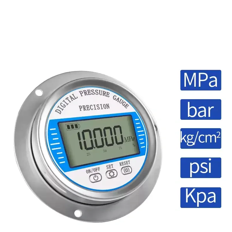
Stainless steel digital pressure gauge with a blue bezel, a four-digit LCD reading 10.000 MPa, and ON/OFF, SET and RESET keys

Digital Pressure Gauges

Digital Pressure Gauge

A battery or 24 V DC digital pressure gauge from 100 kPa to 100 MPa, with a four-digit display, six switchable units and a 304 stainless case for water, air, hydraulic and oil service.

Range
100 kPa to 100 MPa across the range, with 0-0.6, 0-1, 0-1.6, 0-2.5, 0-40, 0-60 and 0-100 MPa as the common spans
Accuracy
0.2, 0.4 or 0.5 class depending on the form
Display
Four digits with up to three decimal places, six switchable units and a backlight
Process connection
M20 x 1.5 as standard, with NPT 1/4 and G1/2 to order
Yellow rectangular water tank with an aluminium pump body on top, a chrome lever with a black grip, a small pressure gauge, a red relief knob and a coiled orange hose

Pressure Test Pumps

Manual Pressure Test Pump

Hand-operated hydrostatic test pump with an 18 litre tank, a brass check valve and a reinforced hose, used to pressure-test water pipe, underfloor heating loops and plumbing installations.

Application
Pressure testing of PPR water pipe, mains pipe, underfloor heating loops and plumbing installations
Gauge fitted
25 MPa on the standard version; a 7 MPa oil gauge on the upgraded version; 40 or 60 MPa on the enlarged version
Tank
18 litres, iron, 1.35 mm wall, sprayed finish, 300 × 200 × 90 mm
Pump body
Aluminium; thickened on the upgraded and enlarged versions
Square indoor air quality monitor with a black face, showing the time at the top, a semicircular index dial reading 047 between the good and bad ends of the scale, temperature and humidity beside it, and six pollutant rows beneath covering formaldehyde, total volatile organic compounds, benzene, carbon dioxide and the two particle fractions

Air Quality Monitors

Multi-Parameter Air Quality Monitor

Indoor air quality monitor reading formaldehyde, total volatile organic compounds, benzene, carbon dioxide, PM2.5, PM10 and a combined index with temperature, humidity, WiFi app logging and history curves.

Monitored parameters
Formaldehyde, total volatile organic compounds, benzene, carbon dioxide, PM2.5, PM10 and a combined air quality index, plus temperature, humidity, time and date on the flagship version
Sensing elements
Electrochemical for formaldehyde, a micro-electromechanical module for total volatile organic compounds, filtered non-dispersive infrared for carbon dioxide, laser scattering for the particle fractions, and dedicated elements for temperature and humidity
Indicative thresholds
Formaldehyde 0.080, total volatile organic compounds 0.600, benzene 0.030, carbon dioxide 1000, PM2.5 75, PM10 100 and index 100, above which the material calls a reading over the limit; the figures are printed without units
Alarm
An audible alarm sounds on the combined index only; the other parameters do not alarm
Two NTC thermistor probes with stainless steel sensing tips and coiled lead wires, one with a black cable and one with a grey cable

Resistance Temperature Detectors

NTC Thermistor Temperature Probe

Stainless steel NTC thermistor probe with a 10 kΩ element at 25°C and a 3950 K B value, supplied with lead wires and plug terminals for control boards and acquisition modules.

Resistance at 25°C
10 kΩ, ±1%
B constant B25/50
3950 K, ±1%
Thermal time constant
3 s, measured in stirred water from 25 to 50°C
Operating temperature
-30 to 180°C in the parameter table; -20 to 105°C on the main image
Panel-mount PID temperature controller with a red process value display, a green setpoint display and four setting keys

PID Controllers

Panel-Mount PID Temperature Controller

Panel-mount PID temperature controllers in four panel sizes, taking thermocouple, RTD, 4-20 mA or 0-10 V inputs and driving relay, SSR, linear and RS-485 outputs.

Panel sizes
48×48, 48×96, 72×72, 96×96 mm
Input types
K, E, J, R, S, B, N, T, PT, CU; 4-20 mA; 0-10 V
Default input
Type K, changeable in the menu
Output forms
Relay, SSR drive, PID 4-20 mA or 0-10 V, linear 0-10 V or 4-20 mA
Two sheathed temperature probes with metal braided leads and fork terminals, one with two conductors and one with three

Temperature Transmitters

Temperature Transmitter Module

Two-wire temperature transmitter module for RTD and thermocouple inputs, converting the sensor signal to 4-20 mA or 0-10 V from 24 VDC, with 0.2%FS accuracy and zero and span potentiometers.

Input
RTD: Pt100, Cu50, Cu100, Pt1000; thermocouple: B, E, J, K, N, R, S, T, WRe3-25, WRe5-26
Sensor range covered
-200 to 1800°C across the range of input types
Output
Two-wire 4-20 mA as standard; a 0-10 V version is listed separately
Accuracy
0.2%FS
Clamp meter held in one hand by its body, with the orange transformer jaw at the top, a rotary function selector and three function keys below the display, and the two test sockets along the bottom face

3266TA (3 models) · Clamp Meters

AC/DC True-RMS Clamp Meter

Clamp meter range reading current through a 25 mm jaw without breaking the circuit, from an AC-only model up to an AC/DC instrument with true-RMS conversion, 6000 counts and a 100 mF capacitance range.

Jaw opening
25 mm
AC current
1 mA to 600 A on the two AC-only models; 10 mA to 600 A on the AC/DC model
DC current
10 mA to 600 A on the AC/DC model only
AC and DC voltage
AC 1 mV to 600 V; DC 0.1 mV to 600 V
Two digital lux meters side by side, the smaller one in a green case with its sensor on a short stalk, a reading of 455 on the LCD and 23.3 degrees beneath it, and the larger one in a black case with a bigger round sensor head and a display reading 288.5 lux in automatic range

AS803F (5 models) · Light Meters

Digital Lux Meter

Digital lux meter covering 0 to 200,000 lx with a sensor head that rotates through 180 degrees, lux and foot-candle units, data hold, maximum and minimum capture and a separate ambient temperature reading.

Measuring range
0 to 200,000 lx on the four AS instruments; 1 to 100,000 lx on the ST instrument
Resolution
1 lx and 0.1 degrees Celsius on the AS instruments; 0.1 lx on the ST instrument
Accuracy
plus or minus 4 percent of reading plus 10 digits at or below 10,000 lx and plus or minus 5 percent plus 10 digits above it; plus or minus 3 percent plus 5 lx on the ST instrument
Sensor
Silicon photovoltaic cell with a colour-correction filter
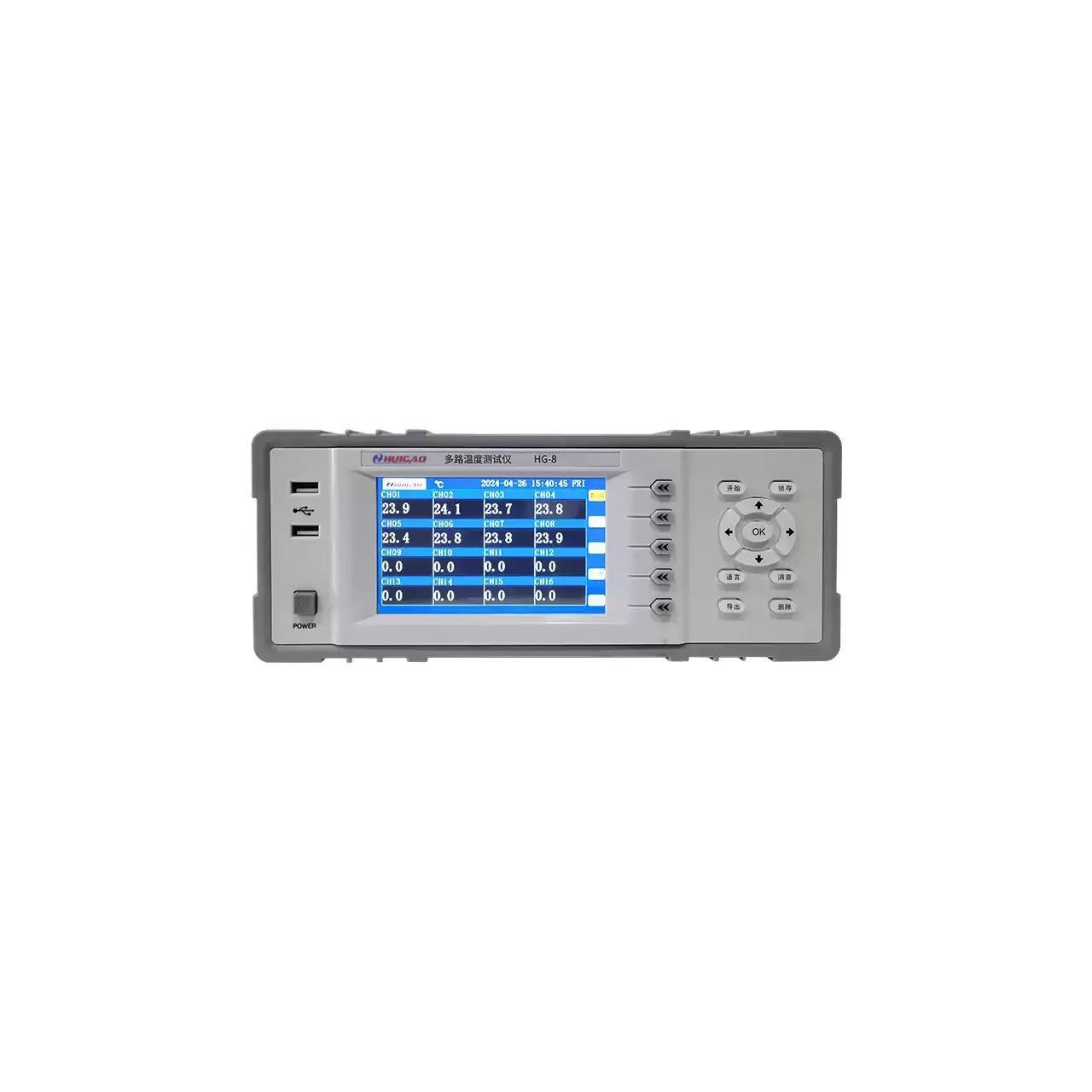
Wide benchtop temperature scanner with a 5 in colour screen showing sixteen channel readings in four columns, two USB sockets at the left, a power switch below them and a keypad with a round OK button at the right

HG-8 (2 models) · Temperature Recorders

Multi-Point Temperature Scanner and Recorder

Eight or sixteen channel thermocouple scanner with a 5 in touchscreen, a scan interval from one second to a day, live-circuit rating and MODBUS RTU communication.

Channels
8 on the HG-8, 16 on the HG-16
Thermocouple types
K, T, J, E, S, N, B and P
Range
−200 to 1350 °C
Accuracy
±0.5% ±0.6 °C
Hand-held gas detector lying at an angle with a flexible metal gooseneck probe rising from its top, a display reading zero against the percentage of the lower explosive limit and naming the gas group, and a vertical row of three keys below it

JLY-CP100 (2 models) · Gas Leak Detectors

Combustible Gas Leak Detector

Portable combustible gas leak detector reading 3 to 20 percent of the lower explosive limit with a flexible gooseneck probe, a three-way alarm and a full-colour display.

Detection range
3 to 20 percent of the lower explosive limit, with sub-ranges of 0 to 1000 ppm and 0 to 100 percent of the lower explosive limit
Alarm set point
10 percent of the lower explosive limit
Indication error
plus or minus 5 percent of the lower explosive limit
Gases
Methane, natural gas, biogas, hydrogen, coal gas, acetone, petrol and ethanol, with the material also naming oxides and sulfides and stating that organic combustible vapours from liquids such as petrol are detected
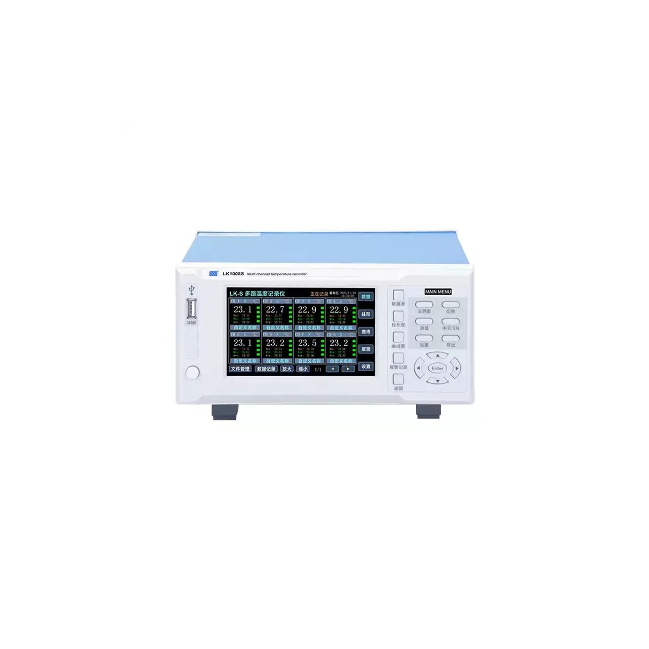
Benchtop temperature recorder with a 5 in colour screen showing eight channel readings in two rows above a row of file and view keys, a USB socket at the left and a keypad with a round Enter button at the right

LK1008S (4 models) · Temperature Recorders

64-Channel Temperature Recorder

Temperature recorder built from 8 to 64 channels, with 8 GB flash memory that holds data through a power cut, four-level alarms and a choice of a 5 in keyed or 7 in touch panel.

Channels
8, 16, 24, 32, 40, 48, 56 or 64
Accuracy
0.2% ±2 digits, thermocouple excluded; the model cards state 0.2% + 0.5 °C
Display range
−999.9 to 1999.9
Probes
Type K supplied; S, R, N, E, J, T, B, PT100, PT1000 and Cu50 by type
Three stainless steel pressure transmitters side by side, one with a plug connector, one with a plug and tubular body, and one with a circular connector and cable gland

MIK-P300 · Pressure Transmitters

Configurable Pressure Transmitter

Diffusion silicon pressure transmitters built in a family of housings, from a plain plug version to sanitary, high-temperature, explosion-proof and 4G wireless forms, with 4-20 mA, voltage or RS-485 Modbus output.

Pressure ranges
-100 kPa to 60 MPa across the series
Pressure types
Gauge, absolute and sealed gauge
Accuracy
0.2, 0.25 or 0.5 grade, by range and configuration
Output
4-20 mA two-wire; 0-5 V, 1-5 V or 0-10 V three-wire; RS-485 with Modbus
Rectangular pressure switch with a transparent scale window showing RANGE and DIFF marks, two adjustment screws, a metal threaded pressure port and a circular push-in fitting on the side

PK503 (3 models) · Pressure Switches

Mechanical Pressure Switch

Mechanical pressure switches with a separate set point and differential screw, SPDT contacts and automatic reset, covering vacuum down to -0.05 MPa and positive pressure to 1.0 MPa in three range versions.

Ranges
PK503 -0.05 to 0.3 MPa; PK506 -0.05 to 0.6 MPa; PK510 0.1 to 1.0 MPa
Adjustable differential
0.035 to 0.15 MPa; 0.06 to 0.4 MPa; 0.1 to 0.3 MPa respectively
Contact form
SPDT, single pole double throw, terminals 1-3-5
Reset
Automatic
Wall-mounted flow meter in a light grey enclosure with a green backlit display showing zero flow, a printed label reading ULTRASONIC FLOWMETER above it, a numeric keypad marked 0 to 9 with menu and enter keys below, five cable glands along the bottom edge, and a pair of clamp-on transducers in blue and white housings lying beside it

SIN-1158S (3 models) · Ultrasonic Flow Meters

Clamp-On Ultrasonic Flow Meter

Clamp-on ultrasonic flow meter for heating, building and process water, supplied as a wall-mounted, handheld or fixed host with clamp-on and insertion transducers.

Model
SIN-1158S / SIN-2100H / SIN-FSC400
Mounting
Clamp-on transducers on the outside of the pipe, or an insertion transducer through the wall
Accuracy
±1 % of full scale, as stated in the material
Pipe range
DN20 to DN1200 according to host and transducer; DN80 to DN6000 with an insertion probe
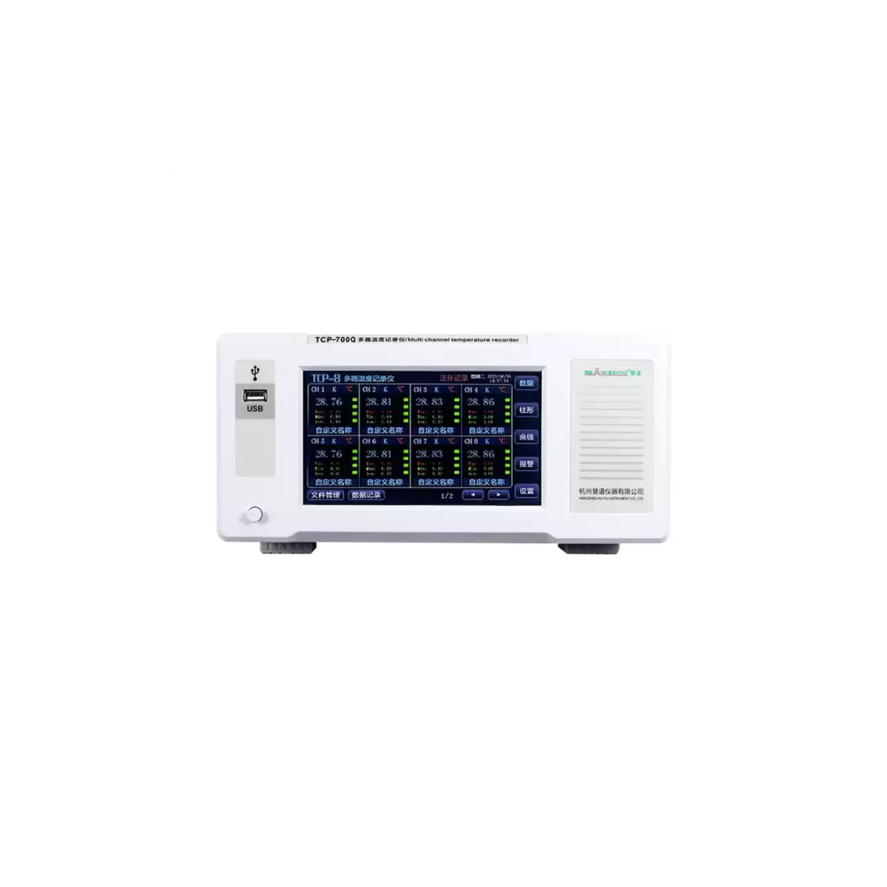
Benchtop temperature recorder seen from the front, with a colour screen showing eight channels of readings in two rows, a USB socket at the left, a round power button below it and a speaker grille at the right

TCP-400 (4 models) · Temperature Recorders

Multi-Channel Temperature Recorder and Scanner

Benchtop multi-channel temperature recorder for 8 to 64 thermocouple inputs, with a colour touchscreen, per-channel correction, four-level alarms and USB logging.

Channels
8 to 64, added in blocks of eight
Thermocouple types
K, S, R, B, N, E, J, T; W5/26 on the XL, 500 and 700 series
Display accuracy
0.2% + 0.5 °C ±2 digits, thermocouple not included
Temperature range
−270 to 2310 °C as marked on most units; a second listing gives −200 to 1300 °C
Stainless steel pressure transmitter with a plug connector on top, a hex body and a threaded pressure port

TFD-801 · Pressure Sensors

Diffusion Silicon Pressure Transmitter

Diffusion silicon pressure transmitters with a 304 stainless steel body, IP65 sealing and ranges from -100 kPa to 100 MPa, in two-wire 4-20 mA and three-wire voltage forms.

Pressure ranges
-100 kPa to 100 MPa across the series
Pressure types
Gauge, absolute and sealed gauge
Accuracy
0.2%FS on the stocked ranges; a 0.5% grade is listed for the series
Output
4-20 mA two-wire as standard; 0-5 V, 0-10 V or RS-485 to order
Black cased circular pressure gauge with a white dial graduated to 1.6 MPa, a red tipped pointer and a brass threaded connection below the case

Y-60 (2 models) · Pressure Gauges

Bourdon Tube Pressure Gauge

Bourdon tube pressure gauges in 60 mm and 100 mm dial sizes with brass connections, covering vacuum to 40 MPa on the 60 mm dial and offered across a wide range list on the 100 mm dial, in iron and stainless steel cases.

Dial sizes
60 mm (Y-60) and 100 mm (Y-100); a 150 mm size is named without a parameter table
Accuracy class
2.5 class on the 60 mm dial; 1.6 class on the 100 mm dial
Range, 60 mm dial
0-0.1 MPa up to 0-40 MPa in fourteen steps, plus -0.1-0 MPa vacuum
Range, 100 mm dial
0-0.1 MPa up to 0-60 MPa listed for the series, with compound and vacuum forms
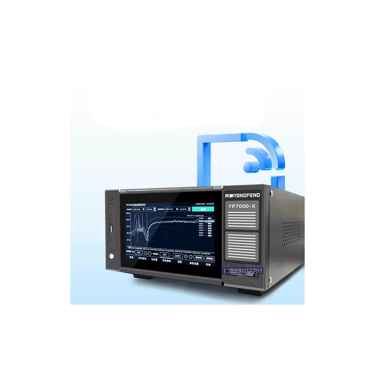
Benchtop recorder with a wide colour screen showing a multi-channel trend plot and a row of page tabs, a USB socket at the left, a round power button beneath it and a vent grille on the right of the front panel

YP4000 (3 models) · Temperature Recorders

Paperless Multi-Channel Temperature Recorder

Touchscreen temperature recorder for 8 to 64 isolated inputs, with four-level alarms, internal storage that survives power loss and wireless viewing from a PC or phone.

Channels
8 to 64, by series
Scan interval
0.1 to 9999 s, adjustable, with three preset speeds
Accuracy
±0.2% ±2 digits, thermocouple excluded
Range
−200 to 1800 °C, sensor dependent

Frequently asked

HVAC Commissioning questions

The questions that come up before an order. If yours is not here, send it with the duty and we will answer it alongside the quotation.

Why is differential pressure used so much in HVAC work?

It is the most direct indicator of whether a filter is loaded, a coil is fouled or a fan is delivering. It requires two pressure connections rather than a full flow measurement, which makes it fast and inexpensive to take, and for troubleshooting that speed matters more than absolute flow accuracy.

Why does the operating condition have to be recorded?

Because a system is rarely at design load when the engineer is on site. A flow figure taken at part load is not wrong, but it cannot be judged against a design value unless the condition it was taken at is known, and the record is what makes the reading usable later.

Which airflow instrument is practical on site?

It follows from access. A vane anemometer suits an open terminal, a thermal mass probe suits a small duct or a grille, and a pitot traverse suits a large duct where a full velocity profile is needed. Probe length and the hole that can be cut decide as much as accuracy does.

Can a clamp-on meter be used on chilled water pipework?

Often it can, which is the reason it is popular for commissioning: nothing has to be drained or cut. It requires pipe material, wall thickness and liner to be entered correctly, and it depends on a reasonable straight run being available.

Do commissioning instruments need calibration certificates?

Where the readings form part of a handed-over record, yes. That is a contractual question rather than a technical one, and it is easier to settle before the instruments are bought than after the record is questioned.

Is logging worth it for a short visit?

It is where the system cannot be seen at design conditions during the visit. Leaving a logger in place over an operating day captures the peak the visit missed, which is frequently the evidence the handover actually needs.

Quoting for hvac commissioning

Send the measurand, the range and the conditions, and we will confirm the instrument family, the configuration and the lead time.

Request for quotation

Request a quotation - HVAC Commissioning

Send the technical detail and we will confirm availability, lead time and terms. In-stock items ship within 48 hours; customized specifications typically take 2-10 days. Minimum order quantity is 1 pc.

The more of this you can give us, the fewer exchanges are needed before we can quote.
No file chosen
Datasheet, drawing, BOM or photograph. One file, up to 10 MB (PDF, Office, image or ZIP).

By submitting this form you agree that we may contact you about this enquiry. We do not sell or share enquiry data. See our privacy policy.

Items held in stock are dispatched within 48 hours of order confirmation. Customized specifications are produced to order and typically ship within 2 to 10 days. Transit time then depends on the shipping method and destination.

Request a Quote WhatsApp