- Channels
- 8 on the HG-8, 16 on the HG-16
- Thermocouple types
- K, T, J, E, S, N, B and P
- Range
- −200 to 1350 °C
- Accuracy
- ±0.5% ±0.6 °C
- Scan interval
- 1 to 99999 s per scan
- Display
- 5 in full touchscreen, all channels on one page
- Live-circuit rating
- AC 400 V and DC 600 V
- Alarms
- Upper and lower limit per channel, shown by colour change and buzzer
- Communication
- USB as standard; RS-232 or RS-485 to order, MODBUS RTU
- Mains
- AC 220 V ±10%, with a 90 to 265 V option
Sixteen points on one screen is not a convenience, it is a different way of reading a test. The operator sees which channel is out of line at a glance, instead of scrolling through numbers that all look alike.
Product overview
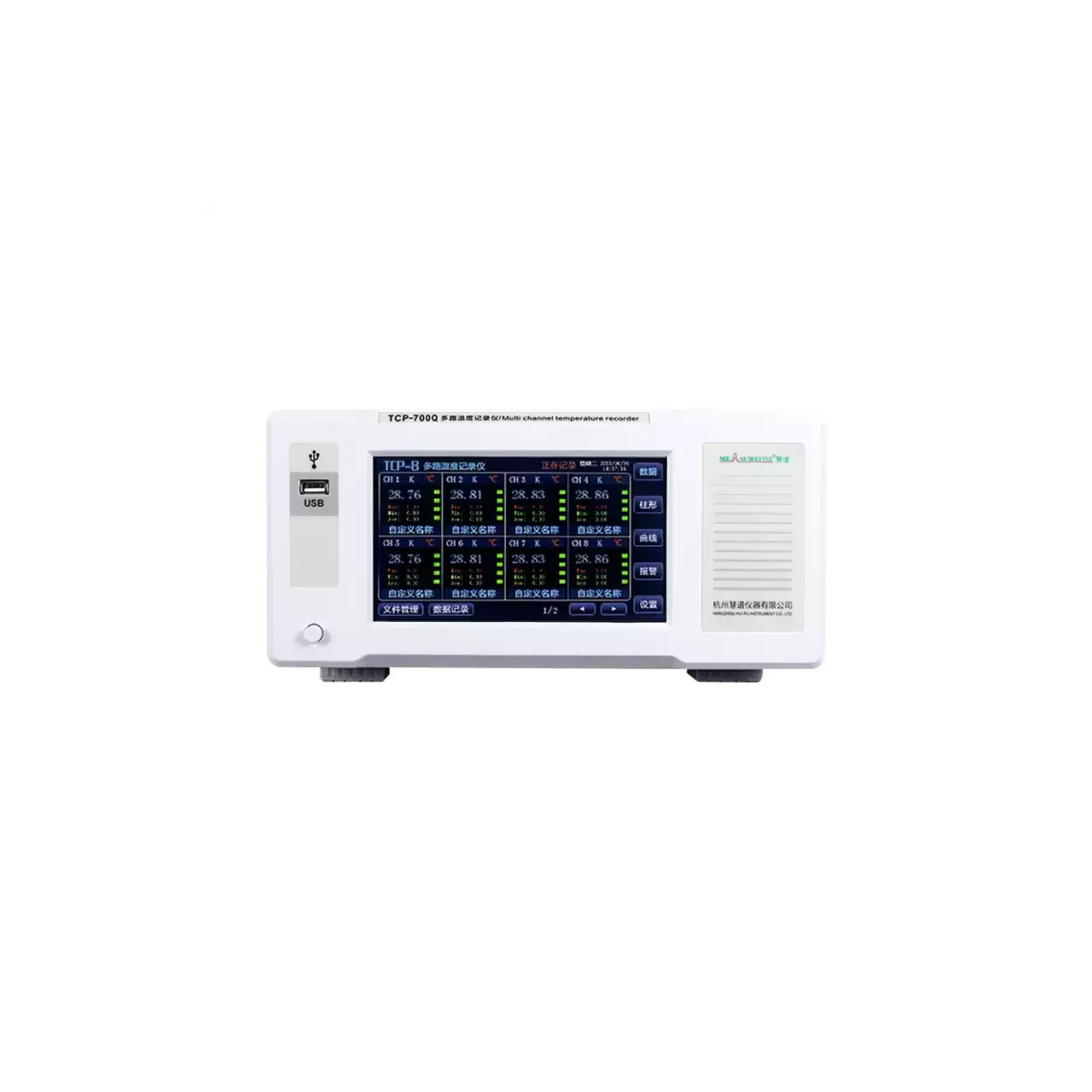
Two models, one panel. The HG-8 carries eight thermocouple inputs and the HG-16 sixteen, on the same 5-inch touchscreen and in the same body. Both accept the same eight thermocouple types and share the same range and accuracy, so the choice between them is a count of points and nothing else.
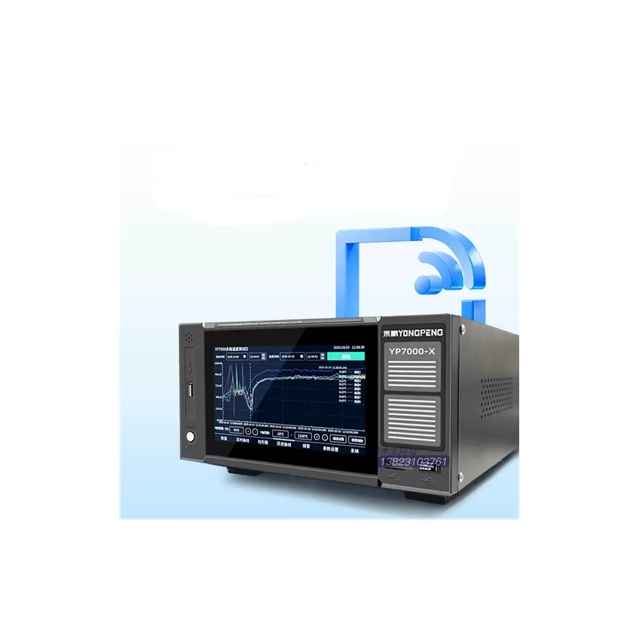
The front panel holds the screen, two USB sockets, the power switch and a keypad with a round OK key and a row of function keys down the side. The rear holds the green thermocouple terminals, the fuse and the mains inlet. A mating thermocouple plug seats directly in the terminal, which keeps a probe change to a plug change rather than a screwdriver job.
The screen shows every channel at once with its tag and its reading. Channels that have crossed a limit change colour, and the buzzer sounds unless it has been muted. There is no curve page: this is an instrument for watching values against limits, not for studying the shape of a profile.
How the multi-point temperature scanner works
The inputs are isolated from one another before they reach the scanner, which is what allows the instrument to sit beside a drive or a contactor panel without the readings moving. Isolation is not the same as accuracy, but on a bench with switching equipment it matters more than another digit of resolution.
The scanner steps through the channels at the interval set on the panel, converts each thermocouple voltage with the curve for the type assigned to that channel, and compares the result with that channel’s upper and lower limits. The comparison happens as the sample is taken, so the alarm and the stored value agree.
Storage is a USB drive in the front socket, with the PC software on it. The same data can leave over the optional serial port in MODBUS RTU, which is the route to take when a PLC or a supervisory system has to see the channels without a person present.
How to select the right scanner
Count the points, then count them again with the ones that will be added later. Eight and sixteen are the only two sizes, and the difference in price is small next to a second instrument or a switched input box, so the larger model is often the calmer purchase.
Check the thermocouple types. All eight are supported on both models, but a probe of a type the instrument does not carry a curve for will read garbage rather than read approximately, so the list matters more than the count.
Then look at what the scanner has to connect to. A USB drive is enough for a report at the end of a shift; a serial link is needed when the readings have to enter a control system. Choose that at the order, because the port is a factory option.
Finally, be honest about the interval. A test that is watched in real time wants seconds; a test that runs unattended for days wants minutes or hours. The setting is one number for all channels, so a mixed test has to be planned around the shortest interval any of them needs.
Measurement limitations and selection considerations
One accuracy figure is quoted for all eight thermocouple types, and that is rarely how thermocouples behave. A type B couple at low temperature and a type K couple at the same temperature do not carry the same uncertainty, and the figure on the label does not separate them. Where the measurement matters, the probe’s own tolerance should be established first.
The live-circuit rating describes the input, not the installation. Whether a probe can be clipped to a live conductor depends on its insulation, its sheath and the condition of its lead, and on whether one end is earthed. A recorder rated for the voltage will still be damaged by a fault path through its terminals.
Scanning is sequential rather than simultaneous, so a fast event appears at different times on different channels. And because there is no curve page, the instrument shows the present state rather than the history: if the shape of a profile matters, a recorder with a trend view is the right instrument and this one is not.
The operating range of the instrument itself also sets a limit. It is specified for a workshop environment, not for a chamber, so a unit placed inside the heated space will fail long before the probes do.
Every value below is taken from source documentation. Where a parameter is not stated in the available material it is marked as information required rather than estimated.