Electrical Test & Measurement · Electrical Test Equipment

Multi-Channel and Multi-Point Resistance Scanner

Bench scanners that step a four-wire measuring circuit through 2 to 64 channels, applying per-channel limits, in ranges from 1 µΩ to 2 MΩ and at up to 40 readings per second.

CXT2518-4 (5 models) ·

Key specifications

Channels
2 to 64 per instrument; 3 to 100 on one family, to order
Measurement
DC resistance, four terminals per channel
Resistance range
1 µΩ to 2 MΩ on the wide families; 10 µΩ to 200 kΩ on the common ones
Accuracy
0.05% typical; 0.02% on one family
Test current
Up to 500 mA; 1 A on one high-speed family
Scan speed
Up to 40 readings per second on a single channel
Channel terminals
HD, HS, LS and LD per channel, on screw terminals or a connector
Interfaces
HANDLER or PLC, RS232, RS485 and USB host

A four-wire meter answers one question at a time. When the thing being tested has sixteen pins, forty windings or sixty-four thermistors, the question is asked sixteen, forty or sixty-four times, and the cost of asking it is the labour, not the instrument.

Product overview

These are bench scanners. Each one contains a single four-terminal resistance measuring circuit and a switching matrix that connects it to each channel in turn, so a fixture can be wired once and scanned in a sequence.

The group spans a wide range of channel counts and two levels of measurement performance. The common families run 4 to 32 channels over 10 µΩ to 200 kΩ at 0.05%, with a 64-channel model on a larger chassis. The wide families reach 1 µΩ to 2 MΩ at 0.02% and add thermal EMF cancellation and a low-voltage mode. The high-speed family pushes 1 A through the part and reads 30 channels a second. One family is offered from 3 to 100 channels to order.

All of them take a fixture on screw terminals, four per channel, and all of them grade each channel against its own limits.

How the multi-channel resistance scanner works

Each channel has four terminals: HD and LD carry the test current, HS and LS sense the voltage. Inside the instrument, a matrix of relays connects the selected channel’s four lines to the single measuring circuit. The instrument closes one channel, waits for the line to settle, measures, compares the result with that channel’s limits, stores the result, and moves to the next.

The settling wait is the part that decides real throughput. A fixture with long unshielded wiring presents capacitance and picks up noise, and the reading needs a moment after the relay closes before it is valid. That is why the families expose a scan delay and a trigger delay rather than quoting a scan time: the same instrument scans a short fixture faster than a long one.

Per-channel ranging matters when the points are not alike. A harness may have a 2 mΩ pin and a 200 Ω pin in the same connector, and a single range would either clip the small one or lose resolution on the large one. The families that select a range per channel handle that; the families with one range for the whole scan are cheaper and suit fixtures where every point is similar.

How to select the right multi-channel resistance scanner

Count the points first, then add the points that will be added next year. Channel count is the one specification that cannot be changed afterwards without a new chassis, and the step from 32 to 64 changes the body size and the screen.

Then look at the spread of resistance across the points. If every point is a similar winding or contact, one range is enough and the common families will do. If the fixture mixes milliohm contacts with hundreds of ohms, per-channel ranging or a wide-range family is the requirement.

Then the accuracy and the current. The 0.05% families cover sorting; the 0.02% family is for a drawing that calls for it. The 1 A family is the one to specify when the lowest point is below 100 µΩ and the part is heavy enough to take the current.

Then the fixture interface. Screw terminals suit a harness built in-house; a connector suits a fixture that is swapped between products. The terminal numbering has to match the channel numbering in the setup, or the results will be assigned to the wrong point, which is the most common way a scanner produces a wrong pass.

Then the output. A scanner that only displays results is a bench instrument; one wired to a handler or PLC is part of a line. Where the fixture will grow past one chassis, cascading over MODBUS is the cheaper route than a larger instrument.

Measurement limitations and selection considerations

The channels are scanned, not sampled together. Two points that must be compared at the same instant cannot be, and a reading that changes during the scan will be captured at different moments on different channels. For a batch of static parts that is irrelevant; for a part that is warming up under load it is not.

Every channel carries its own wiring, and that wiring is part of the measurement. A long channel will read differently from a short one on the same part, because of lead resistance in the drive path and thermal EMF in the sense path. The four-terminal connection removes the first, but not the second, and a fixture that mixes wire types will show a channel-to-channel offset that looks like a product defect.

Thermal EMF is the limiting error at the low end. A relay contact and a copper terminal form a thermocouple, and at 1 µΩ with 500 mA the effect is small but at low current it is not. The families with thermal EMF cancellation or a low-voltage mode are the ones to choose when the bottom of the range is the working point.

Contact resistance at the fixture, not at the instrument, sets the practical floor. A screw terminal that is not tight, or a probe that has lost its spring, produces a reading that drifts between scans and is easy to mistake for a marginal part.

The switching hardware has a life, and the material does not state a contact rating for it. A fixture that scans continuously at 30 readings per second accumulates a large number of operations, so the relay or switch rating should be confirmed for the duty cycle before the instrument is specified into a 24-hour line.

Features

  • One measuring circuit switched across many channels, so every point is measured by the same source and detector and channel-to-channel agreement does not depend on having many instruments
  • Channel counts from 2 to 64 as standard, and 3 to 100 to order on one family, so a fixture with forty points does not need two instruments
  • Per-channel limits, so a harness with different resistance windows at each pin is graded against its own drawing rather than one global limit
  • Screw terminals wired HD, HS, LS and LD per channel, which lets a fixture harness be built once and plugged in
  • Up to 40 readings per second on a single channel, so a 16-point fixture completes a scan in well under a second at the fast setting
  • Handler or PLC outputs per channel, so a sorter can act on the failing point rather than only on the assembly
  • A USB host socket for recording results with the channel number, which is what makes a rework decision possible after the run
  • Cascading over MODBUS on one family, for fixtures that outgrow a single chassis

Technical specifications

Every value below is taken from source documentation. Where a parameter is not stated in the available material it is marked as information required rather than estimated.
Channels and scanning
Channel counts offered2, 4, 6, 8, 12, 16, 32, 40 and 64, depending on familyStandard
Channel count to order3 to 100 on one family; 4 to 40 on the high-speed familyMade to order
Scan modeSequential, one channel at a time through a switching matrixStandard
Per-channel range selectionAutomatic range selection per channel on some families; one range for all channels on othersStandard
Channel setupLimits and range stored per channel; 5 stored parameter sets on most familiesStandard
Trigger delay and scan delayTrigger delay 0 to 999 ms; scan delay 0 to 200 ms, on the family that states themStandard
CascadingSeveral instruments can be chained over MODBUS to extend the channel count, on one familyOptional
Measurement
Measurement parameterDC resistanceStandard
Terminal configurationFour terminals per channel: HD and LD drive, HS and LS senseStandard
Resistance range, common families10 µΩ to 200 kΩStandard
Resistance range, wide families1 µΩ to 2 MΩStandard
Resistance range, extended family1 µΩ to 30 MΩ on the model cards of one family, without a full parameter tableInformation required
Basic accuracy0.05% on most families; 0.02% on one; 0.02% claimed on a principle page for a 0.05% familyStandard
Test currentUp to 500 mA on most families; up to 1 A on the high-speed family; 8 or 9 current stepsStandard
Resolution1 µΩ on most families; 0.1 µΩ stated as the display resolution on oneStandard
Thermal EMF cancellationFitted on one family; listed as not fitted on the othersOptional
Low-voltage measurementOpen-circuit ≤60 mV on the channel range that offers itOptional
Contact checkDetects a poor connection at the channel terminals, where fittedOptional
Sorting and output
ComparatorUpper and lower limits per channel; pass, over and under indicationStandard
Signal outputHI, PASS and LO lines per channel; PASS1 to PASS3 on one familyStandard
BeeperPass, fail or offStandard
CountersPass and fail counts per run, on the families that list themStandard
Limit entryAbsolute limits, or percentage limits against a nominal valueStandard
Interfaces and data
ParallelHANDLER or PLC port, 25-pin, for a sorter or a PLCStandard
SerialRS232 standard; RS485 optional or standard depending on familyStandard
USBUSB host for a memory stick and firmware update; USB device on some familiesStandard
ProtocolMODBUS RTU where stated; SCPI on one familyOptional
Data storageTest results to a USB stick, with the channel number, on most familiesStandard
Display, body and environment
Display4.3-inch colour LCD on 4 to 32 channels; 7-inch on the 64-channel model of one family; 480 × 272 or 800 × 480, depending on familyStandard
Reading digits4½ digits on most families; 5½ on oneStandard
WiringScrew terminals, conductor 18 to 26 AWG, strip length 4.5 mm; wire supplied by the userStandard
Mains198 to 242 V AC, 47 to 63 Hz on most families; 220 V ±10% on twoStandard
Operating environment0 to 40 °C, below 90% RH on most families; below 80% RH on oneStandard
Small body215 × 86 × 330 mm, about 3.6 kg on the compact chassis
Large body400 × 350 × 130 mm, about 8 kg at 32 channels
Single-channel models in the same folder
CH2516Single-channel meter, 1 µΩ to 2 MΩ, ≤1 A, RS232 and handlerStandard
CH2516ASingle-channel meter, 1 µΩ to 200 kΩ, ≤1 AStandard
CH2516BSingle-channel meter, 10 µΩ to 20 kΩ, ≤100 mAStandard
CH2515Single-channel meter, 0.1 µΩ to 110 MΩ, 0.01%, 5½ digitsStandard
CH2515ASingle-channel meter, 1 µΩ to 20 MΩ, 0.01%, 5½ digitsStandard

Available models

Selection table
Model Configuration Key ranges Availability
CXT2518-4 / CXT2518-8 / CXT2518-16 / CXT2518-32 / CXT2518-64 Scanner with 4.3-inch LCD, 64 channels on a 7-inch screen 10 µΩ to 200 kΩ at 0.05%; test current ≤500 mA 4½ digits; 40, 20 and 12 readings per second
CXT2519-4 / CXT2519-8 / CXT2519-16 / CXT2519-32 / CXT2519-64 Scanner with thermal EMF cancellation and contact check 1 µΩ to 2 MΩ at 0.02%; test current ≤500 mA 5½ digits; low-voltage mode at ≤60 mV
CXT2519H-4 / CXT2519H-8 / CXT2519H-16 / CXT2519H-32 Extended-range scanner, model cards only 1 µΩ to 30 MΩ at 0.02% Absent from the parameter table; range needs confirmation
HG2515B / HG2515B-4 / HG2515B-8 / HG2515B-16 / HG2515B-32 / HG2515B-64 / HG2515B-103 Scanner with four speed settings and a colour screen 10 µΩ to 2 MΩ at 0.05%; DC 100 mA to 1 µA 3 to 100 channels to order; PLC and RS232 standard
HG2525B / HG2525 / HG2525B-4 / HG2525B-8 / HG2525B-16 / HG2525B-32 / HG2525B-64 Thermistor scanner with conventional, reference, compare and two-channel modes 10 µΩ to 2 MΩ at 0.05% The same hardware as HG2515B with the thermistor modes; HG2525 appears on one parameter sheet
HG7515B-2 / HG7515B-4 / HG7515B-6 / HG7515B-8 / HG7515B-12 / HG7515B-16 / HG7515B-32 / HG7515B-40 High-speed scanner with 1 A test current 1 µΩ to 2 MΩ at 0.05%; DC 1 A to 1 µA in 9 steps 30 readings per second; 4 to 40 channels to order, though the 2-channel model is listed
RK2518-4 / RK2518-8 / RK2518-16 / RK2518-32 Sequential scanner with PT1000 temperature input 10 µΩ to 200 kΩ at 0.05%; test current 500 mA 40 readings per second on 4 to 16 channels, 35 on 32
LK2518-4S / LK2518-8S / LK2518-16S / LK2518-32S Sequential scanner, five interfaces as standard 10 µΩ to 200 kΩ at 0.05%; test current 500 mA 40, 20 and 12 readings per second; 5 stored setups
CH2518-4 / CH2518-8 Multi-channel version of the single-channel meter 10 µΩ to 200 kΩ at 0.05%; test current ≤500 mA 40 readings per second; 4½ digits

Customization

  • Channel count made to order between 3 and 100, or between 4 and 40 on the high-speed family
  • Fixture harness and terminal numbering to match the customer's point list
  • Extra chassis cascaded over MODBUS where more points are needed than one instrument carries

Certification and compliance

Certification documents not yet supplied

Certifications are only published once a certificate copy can be produced, so this section is deliberately empty rather than populated with assumed approvals. Tell us which approvals your application requires and we will confirm what is available for this instrument.

Parameters still to be confirmed

The following are required for a complete specification but are not stated in the documentation supplied to us. They are listed rather than estimated:

  • The full parameter table for CXT2519H models, whose 1 µΩ to 30 MΩ range appears only on model cards
  • Whether the CXT2518 family has thermal EMF cancellation and contact check, listed as not fitted in the parameter table and claimed as automatic detection on a summary page
  • Whether the 10-bin sorting and RS485 interface are standard or optional on the CXT2518 and CXT2519 families
  • The complete current step list for each family, given only as an end-to-end span with a step count
  • The channel-to-channel switching time and the complete scan time for a 16 or 32 channel fixture
  • Whether the HG7515B-2 two-channel model is built to the same specification as the 4 to 40 channel range it sits outside of
  • Whether the HG2525 designation and the HG2525B designation refer to the same instrument
  • The resistance range of the RK2518: 10 µΩ to 200 kΩ in the parameter table or 10 mΩ to 200 kΩ on the summary page
  • The body dimensions and weight of the RK2518, given as two different sets
  • The display resolution of the RK2518 4 to 16 channel models: 480 × 272 or 480 × 720
  • The weight of the CH2518 multi-channel models and their complete packing list
  • Calibration certificate availability, interval and reference standard
  • Warranty period and terms

Frequently asked questions

How long does a full scan take?

The quoted speed is per channel, so the scan time is the channel count multiplied by the per-channel measurement time, plus the switching and settling delay between channels. A 16-channel scan at 40 readings per second is under half a second of measurement; the practical figure is longer, and the trigger and scan delays are there to be set against the fixture. The material does not state a complete scan time, so it has to be measured on the fixture.

Does every channel get its own measuring circuit?

No. The channels share one measuring circuit and are connected to it in turn by a switching matrix. That is what keeps the channels consistent with each other, and it is also why the readings are sequential rather than simultaneous. A fixture that needs the resistance of several points at the same instant needs a different arrangement.

Why do channel counts stop at 64 when 100 is offered?

Because the chassis, the terminal block and the display all grow with the count. The families that offer 64 as a standard model use a larger body and a 7-inch screen at that end; the 3 to 100 channel option is a build-to-order arrangement on a different family, and the terminal arrangement has to be agreed with the order.

What has to be confirmed before a quotation?

The number of points and whether they will grow; the resistance window at each point, since a wide spread may need per-channel ranging; the test current the parts tolerate; the scan time the line allows; whether the fixture uses screw terminals or a connector; and which output the sorter or PLC expects.

Related products

Other models in the same range

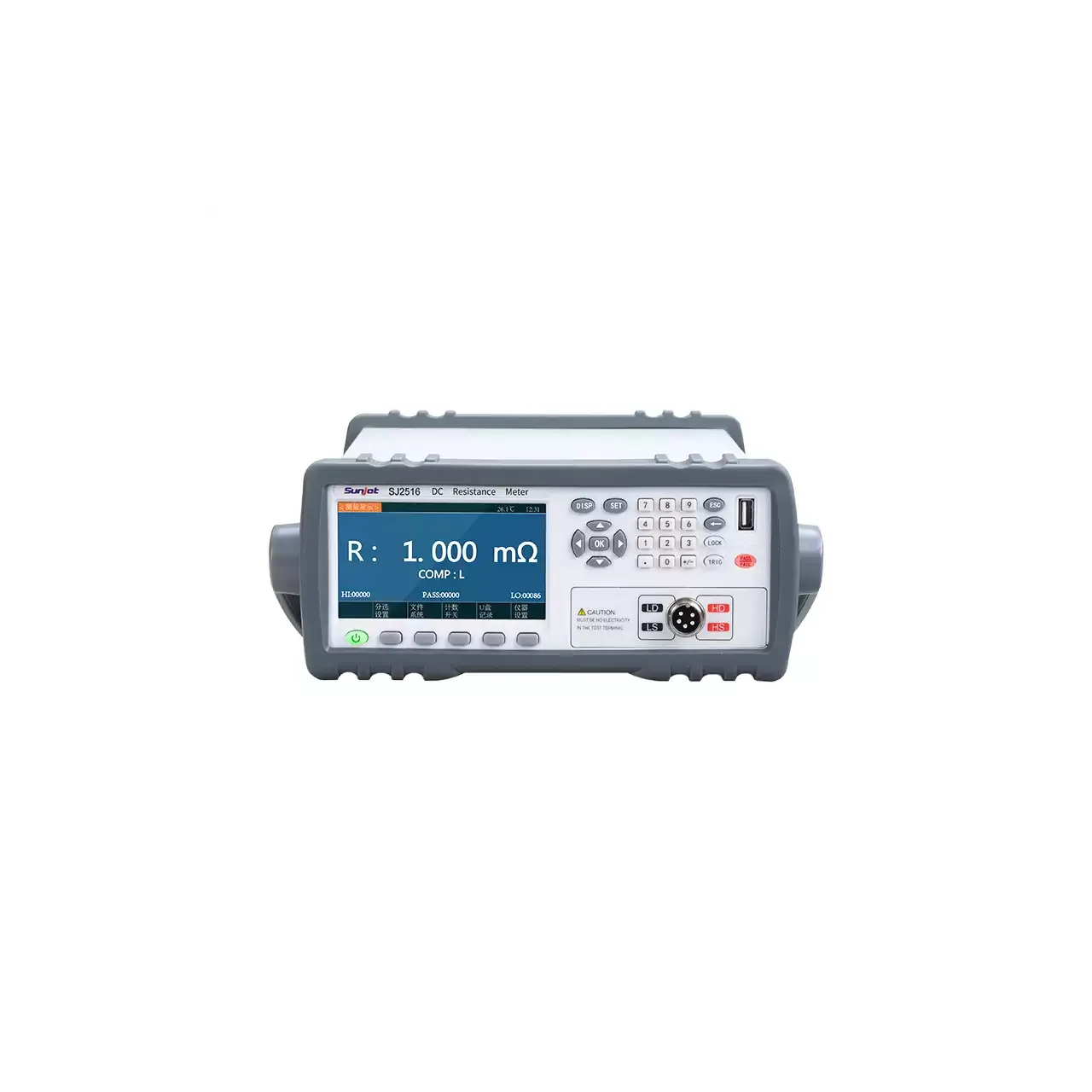
Bench resistance meter seen from the front, with a colour display reading 1.000 mΩ at the left, a numeric keypad at the right and the four test terminals at the lower right

SJ2511 (6 models) · Electrical Test Equipment

Four-Wire DC Low Resistance and Milliohm Meter

Bench four-wire DC resistance meters covering 0.01 µΩ to 2.4 GΩ across the group, with basic accuracy from 0.006% to 0.1%, test current to 10 A and three-level comparator sorting.

Test method
Four-terminal Kelvin, DC test signal
Widest range in the group
0.01 µΩ to 2.4 GΩ
Narrowest range in the group
10 µΩ to 20 kΩ
Basic accuracy
0.006% to 0.1% across the group
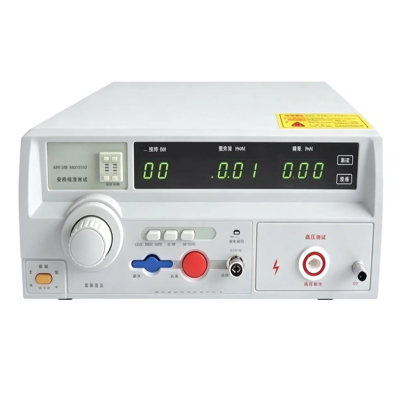
Benchtop high voltage tester seen from the front, with a green segmented readout across the upper right, a large rotary knob at the left, a row of keys with a red stop button below it and a high voltage terminal at the lower right

ZX9320SA-2 (4 models) · Electrical Safety Testers

Multi-Channel Withstand and Insulation Tester

Compact scanning safety tester with two, four or eight channels, AC and DC withstand, insulation resistance to 50 GΩ and nine-level arc detection.

Channels
Two, four or eight depending on model
AC output
0.05 to 5.00 kV, ±2%
DC output
0.05 to 6.00 kV, ±2%, not fitted to AC-only models
Leakage current
AC 0 to 10.00 mA; DC 0 to 10.00 mA on the four-channel model
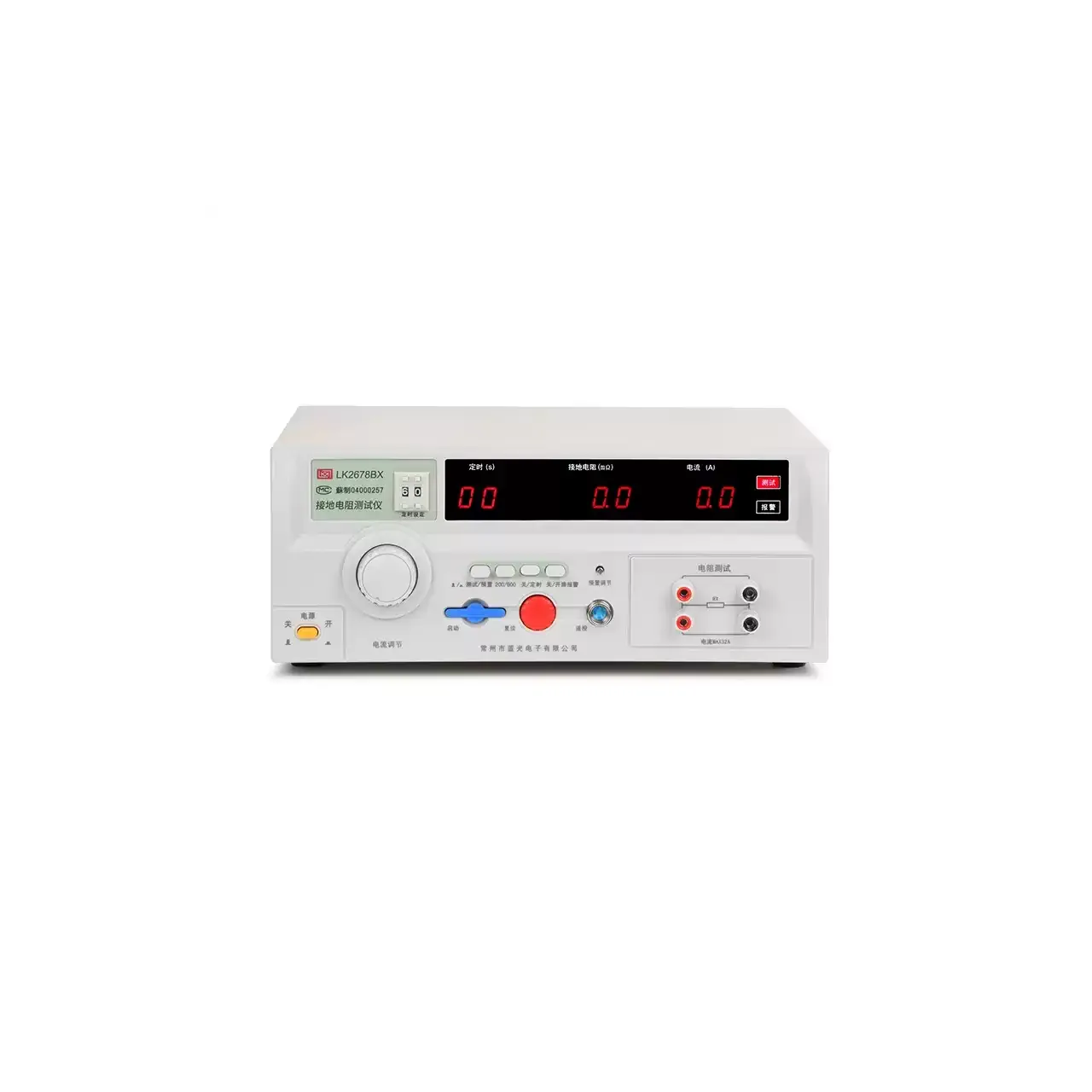
Off-white benchtop tester seen from the front, with a large grey current knob at the left, a black display strip carrying three red digital readouts across the centre, a row of small keys below it and two pairs of red and black terminals on a separate panel at the right

LK2678BX (4 models) · Electrical Safety Testers

Four-Wire Ground Bond Resistance Tester

Four-terminal ground bond tester with 1 to 50 A output across four models, 0 to 600 mΩ ranges, presettable test time and upper limit alarm.

Output current
5 to 32 A on LK2678BX, 10 to 50 A on LK2678, 3 to 32 A on LK7305, 0.01 to 45 A on LK7340
Resistance range
0 to 200 mΩ or 0 to 600 mΩ on LK2678BX and LK2678; 0 to 510 mΩ on LK7305; 0 to 600 mΩ on LK7340
Resistance accuracy
±5% on LK2678BX and LK2678; ±2% on LK7305 and LK7340
Test time
1 to 99 s on LK2678BX, 1 to 999 s on LK2678, 0.1 to 999.9 s on LK7305, 0 or 0.5 to 999.9 s on LK7340

Request a quotation for the CXT2518-4

Send the configuration you need and we will confirm availability, lead time and terms. Minimum order quantity is 1 pc.

Request for quotation

Request a quotation - CXT2518-4

Send the technical detail and we will confirm availability, lead time and terms. In-stock items ship within 48 hours; customized specifications typically take 2-10 days. Minimum order quantity is 1 pc.

The more of this you can give us, the fewer exchanges are needed before we can quote.
No file chosen
Datasheet, drawing, BOM or photograph. One file, up to 10 MB (PDF, Office, image or ZIP).

By submitting this form you agree that we may contact you about this enquiry. We do not sell or share enquiry data. See our privacy policy.

Items held in stock are dispatched within 48 hours of order confirmation. Customized specifications are produced to order and typically ship within 2 to 10 days. Transit time then depends on the shipping method and destination.

Request a Quote WhatsApp