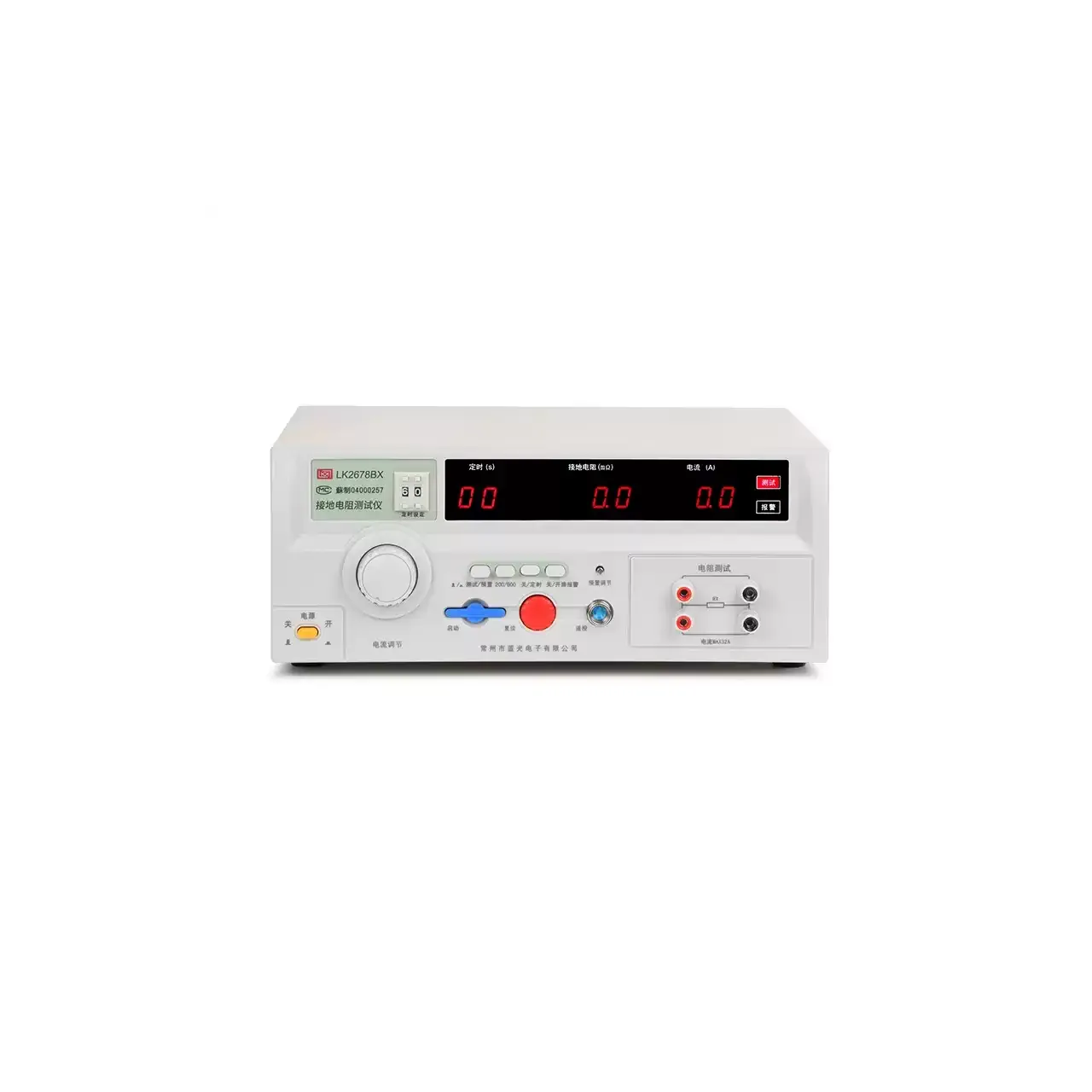
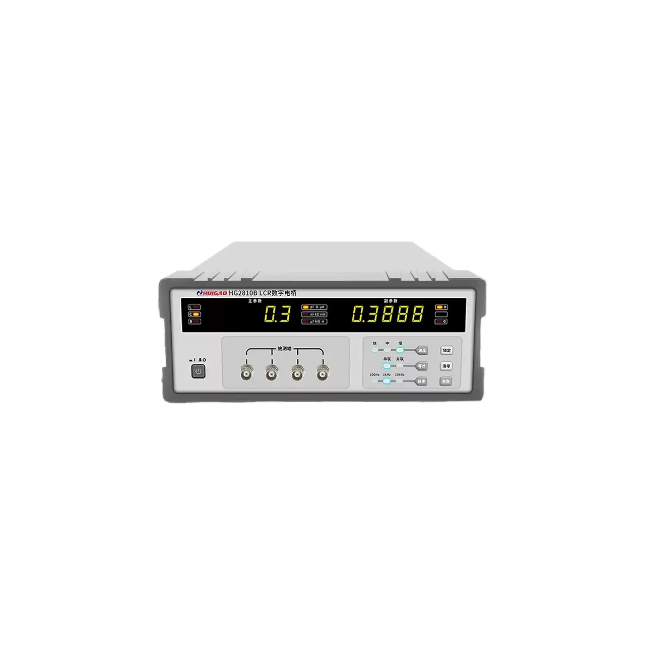
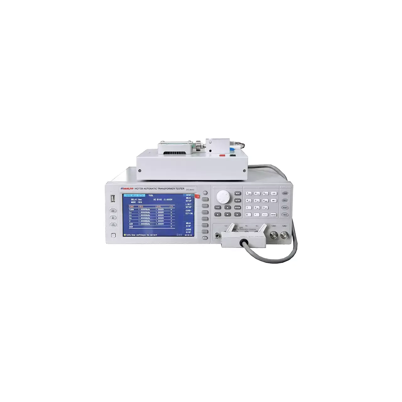
A four-wire resistance meter is bought for one reason: the number on the display has to belong to the part, not to the leads. Every instrument in this group uses the same method to get there. What separates them is how low and how high they reach, how much current they can push, and how the result leaves the box.
Product overview
All of these are single-channel bench meters with a DC test signal and a four-terminal socket. The entry models read 10 µΩ to 20 kΩ at 0.1% on a green LED display; the precision models reach 0.01 µΩ to 2.4 GΩ at 0.006% on a colour screen with 6½ digits. Between those ends sit the compact LCD families, which are the ones usually specified for a sorting bench.
The differences that matter to a buyer are narrower than the model count suggests. Test current runs from 100 µA on the entry units to 10 A on the ultra-low models. Sorting runs from a three-level pass, over and under comparator to fourteen bins. Interfaces run from nothing at all on two entry models to RS232, RS485, USB host and a handler port on the precision units.
How the four-wire resistance meter works
A current is forced through the part on the drive pair, HD and LD. The voltage that current develops across the part is sensed on a second pair, HS and LS, which carries almost no current. Because the sense pair draws nothing, the resistance of the leads and clips never appears in the measured voltage, and the meter can compute the part resistance directly.
That is also why these instruments can be used without zeroing. The offset that a two-wire measurement would show as a floor is not in the sense circuit to begin with; the remaining internal bias is cancelled in hardware, so a shorted clip reads at or near zero. Full-range short-circuit zeroing is still offered as a check rather than as a routine step.
Range and current are tied together. A meter resolves micro-ohms by pushing amps through the part and reading the resulting millivolts; it resolves megohms by dropping to microamps so the voltage stays inside the input range. Selecting a range therefore selects a current, which is why the low ranges carry the highest current and why a part that cannot take that current needs the low-power mode instead.
A comparator compares every reading against stored limits and drives a relay, a handler line or a lamp. On the families with several bins, the reading is graded rather than merely accepted or rejected.
How to select the right four-wire resistance meter
Start at the bottom of the resistance window. Below about 100 µΩ the 1 A families run out of digits and the 10 A models are the reason to move up; between 1 mΩ and 2 Ω almost any family in the group will do; above 200 kΩ only the wide-range models are relevant.
Then take the top of the window. A meter that stops at 20 kΩ will not check a transformer winding or a cable run, and a meter that reaches 2.4 GΩ costs more than the task needs if every part is a connector contact.
Then the accuracy the drawing or the standard calls for. The spread inside this group is a factor of about fifteen, from 0.1% to 0.006%, and it is the single largest price driver after range.
Then the interface. A bench that reads the value by eye needs nothing beyond the display and the pass lamp. A bench that logs needs RS232 or USB host. A line that sorts needs the handler or PLC port, and a PLC that speaks MODBUS needs the family that states it. One family adds a 2 ms mode, which only matters if a handler is moving faster than about thirty parts a second.
Finally, whether the part tolerates the test current. Winding wire, thin film resistors and small thermistors are the usual cases for the low-power mode, where the open-circuit voltage is held at 60 mV or less.
Send the part, both ends of the resistance window, the fixture drawing and the interface the line uses, and the family narrows to one or two models.
Measurement limitations and selection considerations
These are DC resistance instruments. They do not measure inductance or capacitance, and on a winding the reading is the copper resistance only; a bridge is the right instrument when the reactive part matters.
At the bottom of the range the enemy is thermal EMF. A junction of two dissimilar metals generates a few microvolts, which at 0.01 µΩ and 10 A is small but at 1 A is not. The families that list thermal EMF cancellation, or a low-power mode, are the ones to specify when the reading has to hold at the last digit.
Test current heats the part. A 10 A measurement on a small contact will move its resistance during the reading, and repeating the measurement will give a different number each time. High current is for heavy joints, not for fine ones.
Four terminals remove the lead resistance, not a bad contact at the clip. A dirty or loose clip adds noise that looks like an unstable part, which is why several families offer a contact check.
At the top of the range the limit is settling time rather than resolution. A 2 MΩ or 100 MΩ part with a shielded lead behaves like a small capacitor, and the reading needs a moment to settle; the quoted fast speeds apply at the low ranges.
None of these instruments scans multiple points. Where a fixture holds a row of parts that have to be measured in sequence, a scanner is the appropriate instrument and a single-channel meter will only do the job one clip at a time.
Every value below is taken from source documentation. Where a parameter is not stated in the available material it is marked as information required rather than estimated.