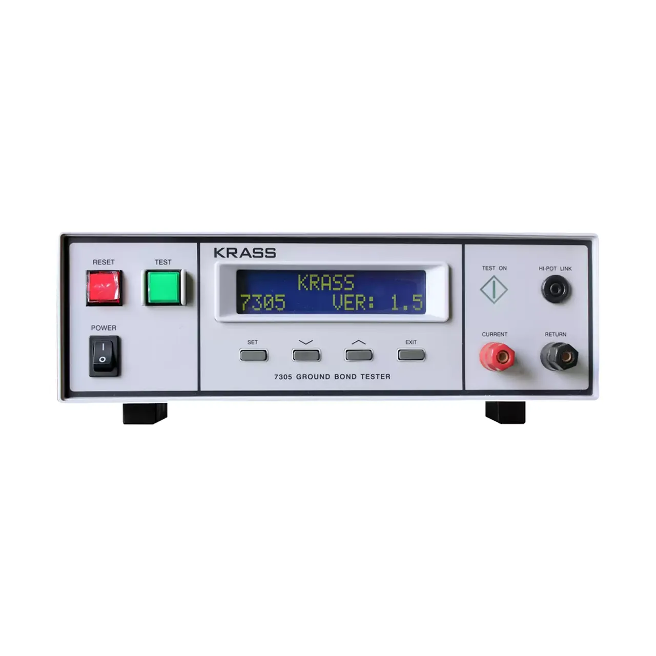
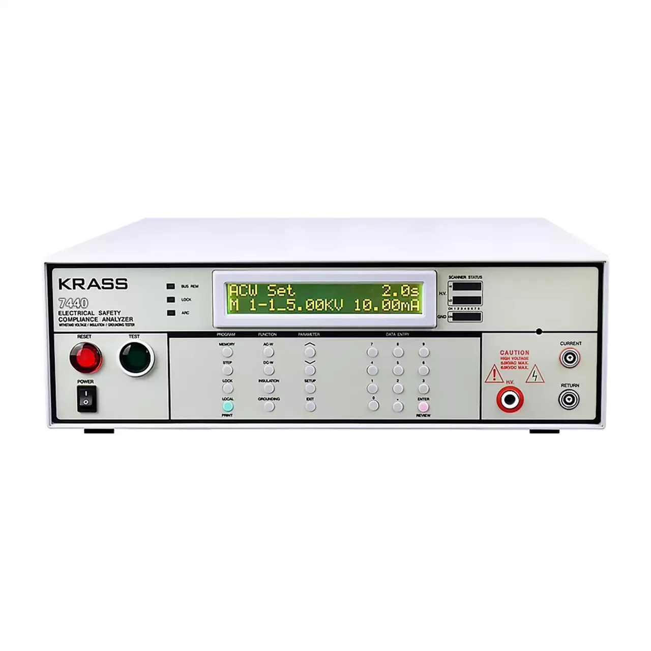
- Output current
- 5 to 32 A on LK2678BX, 10 to 50 A on LK2678, 3 to 32 A on LK7305, 0.01 to 45 A on LK7340
- Resistance range
- 0 to 200 mΩ or 0 to 600 mΩ on LK2678BX and LK2678; 0 to 510 mΩ on LK7305; 0 to 600 mΩ on LK7340
- Resistance accuracy
- ±5% on LK2678BX and LK2678; ±2% on LK7305 and LK7340
- Test time
- 1 to 99 s on LK2678BX, 1 to 999 s on LK2678, 0.1 to 999.9 s on LK7305, 0 or 0.5 to 999.9 s on LK7340
- Terminals
- Separate current output and resistance sense terminals on all four models
- Display
- LED digits for time, resistance and current on the LK2678 series; 16 × 2 backlit LCD on LK7305
- Alarm
- Upper resistance limit settable continuously, with lamp and audible warning
- Remote control
- External start and stop input via a remote connector
- Isolation transformer
- 300 VA on LK2678BX and LK2678; 500 VA on LK7305
- Body
- 275 × 100 × 340 mm, 10 kg on LK2678BX and LK7305; 375 × 195 × 280 mm, 15 kg on LK2678; 340 × 120 × 450 mm, 16 kg on LK7340
A ground bond test answers one question: is the protective connection inside this product low enough in resistance to carry fault current. The answer is only useful if it is repeatable, which is why the current, the hold time and the limit have to be set the same way on every unit. This range is built around that repetition in four current classes.
Product overview
Four models share the same four-terminal measuring arrangement and differ in output current, resistance range, timing resolution and accuracy. Two of them are current-grade instruments at ±5%, two are higher-grade at ±2%, and the largest reaches 50 A.
The front panel puts the current control at the left, the readouts across the centre and the current terminals on a separate panel at the right, so the leads run away from the controls rather than across them. The case is a bench body with a carry handle; the two 10 kg models can be lifted by one person, the 15 kg and 16 kg models are better treated as fixed bench instruments.
How the ground bond tester works
A test current is forced through the protective conductor and the point it is bonded to. The voltage that appears across that path is sensed on a second pair of leads, and the resistance follows from the two readings.
The second pair is what makes the measurement useful. On a bond of fifty milliohms, the resistance of the leads and clamps can be comparable to the bond itself, so a two-terminal reading would describe the fixture as much as the product. With a separate sense pair almost no current flows in the voltage circuit, so almost no voltage is dropped in it, and the instrument reads the bond.
The reading is then compared with an upper limit set on the front panel. Above it, the bond is too resistive and the instrument lights the fail lamp and sounds a long tone. On the LK7340 a lower limit can also be set, which catches an open circuit that would otherwise read as a very good bond.
How to select the right ground bond tester
Start with the test current in the product standard. Thirty-two amps covers most appliance and electronic assembly work, which is where LK2678BX and LK7305 sit. A standard that calls for 40 A or more moves the choice to LK7340 at 45 A or LK2678 at 50 A.
Accuracy is the second question. The ±2% models are the ones to specify when the limit in the standard is close to the resistance of a good sample, because a ±5% instrument eats a large part of that margin. Where the limit is generous, the current-grade models do the same job.
Timing is the third. A test of one or two seconds is served by any model; a test that has to be held for minutes, or watched while the reading settles, needs the 999.9 s setting and, on the LK7340, the continuous setting at zero.
The last is the fixture. Lead length, clamp type and terminal spacing all have to be stated with the order, since the standard accessory is the only lead set the material lists.
Measurement limitations and selection considerations
The instrument measures the bond as it exists at that moment. A joint that passes cold can fail after thermal cycling, and a screw tightened on the bench can loosen in a vibrating assembly, so the test characterises the sample in front of it rather than the product in service.
Contact quality dominates the low end. Probe placement, surface finish and clamp pressure can move a reading by more than the instrument error, and four-terminal sensing removes the lead but not the contact. Comparable readings over time require the same jig and the same probe position.
Current heats the bond and the leads. The material states no duty cycle, so the rate at which tests can be repeated at the top of the current range has to be agreed before a line is planned around the instrument.
Finally, this is a bond test and not a dielectric test. It says nothing about insulation strength, leakage current or power consumption, and a product that needs those checks needs a separate safety tester rather than a higher current setting on this one.
Every value below is taken from source documentation. Where a parameter is not stated in the available material it is marked as information required rather than estimated.