Electrical Test & Measurement · Electrical Safety Testers

Programmable Ground Bond Resistance Tester

Programmable ground bond tester with a regulated AC test current, settable resistance limits, self-zero lead correction and PLC remote control in three current classes.

7305 (3 models) ·

Key specifications

Output current
3 to 33 A on 7305, 1 to 40 A on 7314, 1 to 60 A on 7316
Maximum output voltage
6 V on 7305, 8 V on 7314, 12 V on 7316
Resistance range
0 to 510 mΩ on 7305; 0 to 600 mΩ on 7314 and 7316
Frequency
50 or 60 Hz, selectable, ±100 ppm
Program memory
Five groups on 7305, ten groups on 7314 and 7316
Display
16 × 2 character LCD on 7305, 128 × 64 LCD on 7314 and 7316
Test time
Up to 999.9 s, continuous at zero
Remote control
PLC start, stop and reset inputs; pass, fail and processing outputs
Standard accessory
7300 test lead set, listed for all three models

A ground bond test is a pass or fail judgement about a protective connection, and it is only worth repeating if the current, the hold time and the limit are the same on every unit. This range is built around that repetition, with output current as the main difference between the three models.

Product overview

Three models share one control layout. The smallest runs a bond test at a lower current and holds fewer programs; the two larger ones extend the current and add a graphic display with a longer program memory. All three apply an alternating current through the bond, read the resistance and compare it with an upper limit for a pass and a lower limit for a valid connection.

The front panel carries the start and reset buttons at the left, the display and four setup keys in the centre, and the current and return terminals at the right. The rear carries the mains voltage selector, the fuse holder, the earth stud and the two nine-pin connectors for remote control in and out.

How the ground bond tester works

A regulated alternating current is forced through the protective conductor and the point it is bonded to, and the voltage that appears across that path is measured at the same moment. The resistance follows from the two readings, and the instrument compares it with the limits the operator has entered. Above the upper limit the bond is too resistive and the test fails; below the lower limit the circuit is usually open, which is why a floor is set as well as a ceiling.

The sensed voltage includes the drop across the test leads and the clamps, and on a bond of a few milliohms that drop can be the larger part of the reading. The instrument therefore provides a self-zero correction: the lead resistance is measured and subtracted before the test, either automatically or as a manually entered offset.

Current is regulated rather than simply switched on, which is why the output is quoted as an accuracy on the setting instead of a band around a nominal value. A regulated current also means the reading does not drift as the bond heats and its resistance rises during the hold.

How to select the right tester

Start with the test current written into the product standard, not with the largest number in the table. That single figure decides between the three models, and choosing above it buys nothing except weight on the bench. The two larger models also allow the current to be set in fine steps, which matters when the standard names a current that does not fall on a coarse setting.

The second question is how many products the bench sees. Program memory is the practical limit on changeover: the smallest model holds fewer groups, so a bench that alternates between several products through a shift will spend time re-entering parameters that the larger models would have stored.

The third is the interface. All three accept a remote start and report pass or fail, and several instruments can be run in step from one controller, which is what a multi-point fixture needs. If the operator reads the value rather than the verdict, the graphic display of the larger models shows more at once.

The last is the site supply. The three models are marked for different input ranges and the selector on the rear only covers the voltages the model supports, so the supply has to be confirmed before the order rather than at commissioning.

Measurement limitations and selection considerations

The instrument measures the path that exists at the moment of the test. A bond that passes on a cold sample can fail after thermal cycling, and a screw that was tightened to torque on the bench can loosen in a vibrating assembly, so the test is a check on the sample in front of it rather than a prediction of service life.

Contact quality dominates the low end of the range. Probe placement, surface finish and the pressure of the clamp can move the result by more than the instrument error, and the self-zero correction removes the lead but not the contact. The same jig and the same probe position have to be used if readings are to be compared over time.

Current heats both the bond and the leads. The material does not state a duty cycle, so the rate at which tests can be repeated at the top of the current range has to be confirmed before a line is planned around the instrument.

Finally, this is a bond test and not a dielectric test. It says nothing about insulation strength, leakage current or power consumption, and a product that needs those checks needs a separate safety tester or a combined instrument rather than a higher current setting on this one.

Features

  • The output current is regulated and quoted as a setting accuracy rather than a tolerance band, so a programmed test current is repeatable from unit to unit
  • Output frequency is selectable between 50 and 60 Hz on all three models, so a test written for one supply frequency can be reproduced on the other
  • A self-zero correction measures the resistance of the test leads and clamps and subtracts it before the test, in automatic or manual offset mode
  • PLC remote control carries start, stop and reset inputs and pass, fail and processing outputs, and several instruments can be run in step from one controller
  • Program memory stores the parameters of products that are run repeatedly, with more groups on the two larger models
  • The keyboard can be locked, which keeps an unauthorised operator out of the parameter settings on a shared bench
  • Test time can be set to run continuously, for a bond that has to be watched while its reading settles
  • The warning volume is settable over nine steps, with zero switching it off for a quiet bench

Technical specifications

Every value below is taken from source documentation. Where a parameter is not stated in the available material it is marked as information required rather than estimated.
Output
Output current, 73053 to 33 A, ±(2% of setting + 2 counts)Standard
Output current, 73141 to 40 A, resolution 0.01 AStandard
Output current, 73161 to 60 A, resolution 0.01 AStandard
Maximum output voltage6 V on 7305, 8 V on 7314, 12 V on 7316Standard
Output frequency50 or 60 Hz, selectable, ±100 ppmStandard
Resistance measurement and limits
Resistance range, 73050 to 510 mΩ, 1 mΩ steps, ±(2% of setting + 2 counts)Standard
Upper and lower limits, 73050 to 510 mΩ over 3.0 to 10.0 A; 0 to 120 mΩ over 10.1 to 30.0 A; 1 mΩ stepsStandard
Measurement accuracy, 7305±(2% of setting + 2 mΩ)Standard
Upper and lower limits, 73140 to 600 mΩ; 0 to 200 mΩ; 0 to 150 mΩ, 1 mΩ stepsStandard
Upper and lower limits, 73160 to 600 mΩ; 0 to 300 mΩ; 0 to 150 mΩ, 1 mΩ stepsStandard
Current segments, 73141.00 to 10.00 A; 10.01 to 30.00 A; 3.01 to 40.00 A as printedStandard
Current segments, 73161.00 to 15.00 A; 15.01 to 30.00 A; 30.01 to 60.00 AStandard
Resistance offset0 to 100 mΩ, automatic or manual, 1 mΩ steps, ±(2% of setting + 2 counts)Standard
Offset resolution and mode1 mΩ; auto or manual offset mode selectableStandard
Timing
Test time, 73050.0 or 5 to 999.9 s (0 = continuous), 0.1 s steps, ±(0.1% + 0.05 s)Standard
Test time, 7314 and 73160 or 0.5 to 999.9 s (0 = continuous), 0.1 s resolutionStandard
Warning volume0 to 9, where 0 switches the warning offStandard
Interface and memory
Program memoryFive groups on 7305; ten groups on 7314 and 7316Standard
Display16 × 2 character LCD on 7305; 128 × 64 LCD on 7314 and 7316Standard
Remote inputStart, stop and withstand test on 7305; test, reset and withstand processing on 7314 and 7316Standard
Remote outputPass, fail, testing, reset trigger and start trigger on 7305; pass, fail, processing, reset out and start out on 7314 and 7316Standard
Keyboard lockParameter entry can be locked against unauthorised changeStandard
CalibrationSoftware calibration entered from the front panelStandard
Supply, body and environment
Input supply, 7305110/220 V AC ±10%, 50/60 Hz ±5%Standard
Input supply, 7314 and 7316115/230 V AC ±15%, 50/60 Hz ±5%Standard
Fuse3.15 A for 7305 and 7315 as printed; 10 A for 7314 and 7316Standard
Dimensions, 7305280 × 89 × 370 mmStandard
Dimensions, 7314 and 7316215 × 89 × 430 mmStandard
Net weight10 kg on 7305; 15 kg on 7314 and 7316Standard
Second size and weight reading215 × 89 × 430 mm and 15 kg printed in the general specification row of the 7305 table as wellStandard
Operating environment0 to 40 °C, 20 to 80% RHStandard
Calibration certificateNot stated in the materialInformation required
Ingress protectionNot stated in the materialInformation required

Available models

Selection table
Model Configuration Key ranges Availability
7305 Smallest current class, character display 3 to 33 A; 0 to 510 mΩ; five program groups For routine chassis and enclosure bonds
7314 Middle current class, graphic display 1 to 40 A; 0 to 600 mΩ; ten program groups Current settable in 0.01 A steps
7316 Largest current class, graphic display 1 to 60 A; 0 to 600 mΩ; ten program groups For bonds that must carry the highest current in the range

Customization

  • Test lead sets built for a particular fixture or terminal spacing
  • Synchronised operation of several instruments from one PLC

Certification and compliance

Certification documents not yet supplied

Certifications are only published once a certificate copy can be produced, so this section is deliberately empty rather than populated with assumed approvals. Tell us which approvals your application requires and we will confirm what is available for this instrument.

Parameters still to be confirmed

The following are required for a complete specification but are not stated in the documentation supplied to us. They are listed rather than estimated:

  • Which body size and weight applies to 7305, since the model table gives 280 × 89 × 370 mm and 10 kg while the general specification row of the same table gives 215 × 89 × 430 mm and 15 kg
  • Whether 7315 exists as a fourth model, since it appears in the fuse clause but has no specifications anywhere in the material
  • Whether the third current segment of 7314 is 3.01 to 40.00 A as printed, or 30.01 to 40.00 A, since it does not continue from the segment before it
  • The reason the 7305 upper current limit is 33 A while its limit-setting segments stop at 30.0 A
  • The meaning of the rear socket marking read as 15V to 230V 6.3A MAX, which is probably 115 V to 230 V but could not be verified
  • Calibration certificate availability and the standard it would be issued against
  • Warranty period and its terms
  • Test lead length, current rating and terminal type
  • Duty cycle for repeated tests at the top of the current range
  • Ingress protection rating, which the material does not give

Frequently asked questions

Is a ground bond tester the same thing as an earth resistance tester?

No. A ground bond tester drives a current through a protective conductor inside the product and measures the resistance of that bond, which is a few milliohms to a few hundred milliohms. An earth resistance tester measures the resistance of a rod or electrode to the surrounding soil, which is a different quantity, a different test current and a different set of accessories. The two are used at different stages and are not interchangeable.

Which model suits a test that has to run at 40 A?

7314, whose output reaches 40 A. The 7316 reaches 60 A and is specified for bonds that need more current or a longer hold at the top of the range; the 7305 stops at 33 A and is the smaller of the three. The current written into the product standard decides between them, not the size of the product.

What has to be confirmed before a quotation?

The test current and the hold time the product standard requires, which fix the model; the resistance limit and whether the reading has to be recorded, which decides whether the PLC outputs are used; and the site supply voltage, because the three models are marked for different input ranges. Test lead length and terminal type should also be stated, since the standard lead set is the only accessory the material lists.

Related products

Other models in the same range

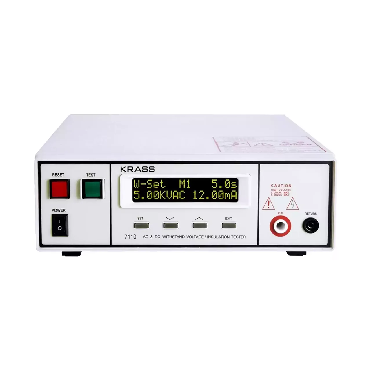
Compact programmable safety tester shown from the front with the two-line LCD at the upper left, a row of function keys beneath it and the test terminals along the lower right

7110 (8 models) · Electrical Safety Testers

Compact AC/DC Withstand Voltage and Insulation Tester

Compact programmable safety tester with 5 kV AC and 6 kV DC withstand voltage, insulation resistance to 9999 MΩ, five stored programs and PLC remote control.

AC output
0 to 5.00 kV, 12 mA
DC output
0 to 6.00 kV, 5 mA, on four of the eight models
Frequency
50 or 60 Hz, selectable
Leakage limits
0.10 to 12.00 mA AC and 0.02 to 5.00 mA DC, upper and lower set independently
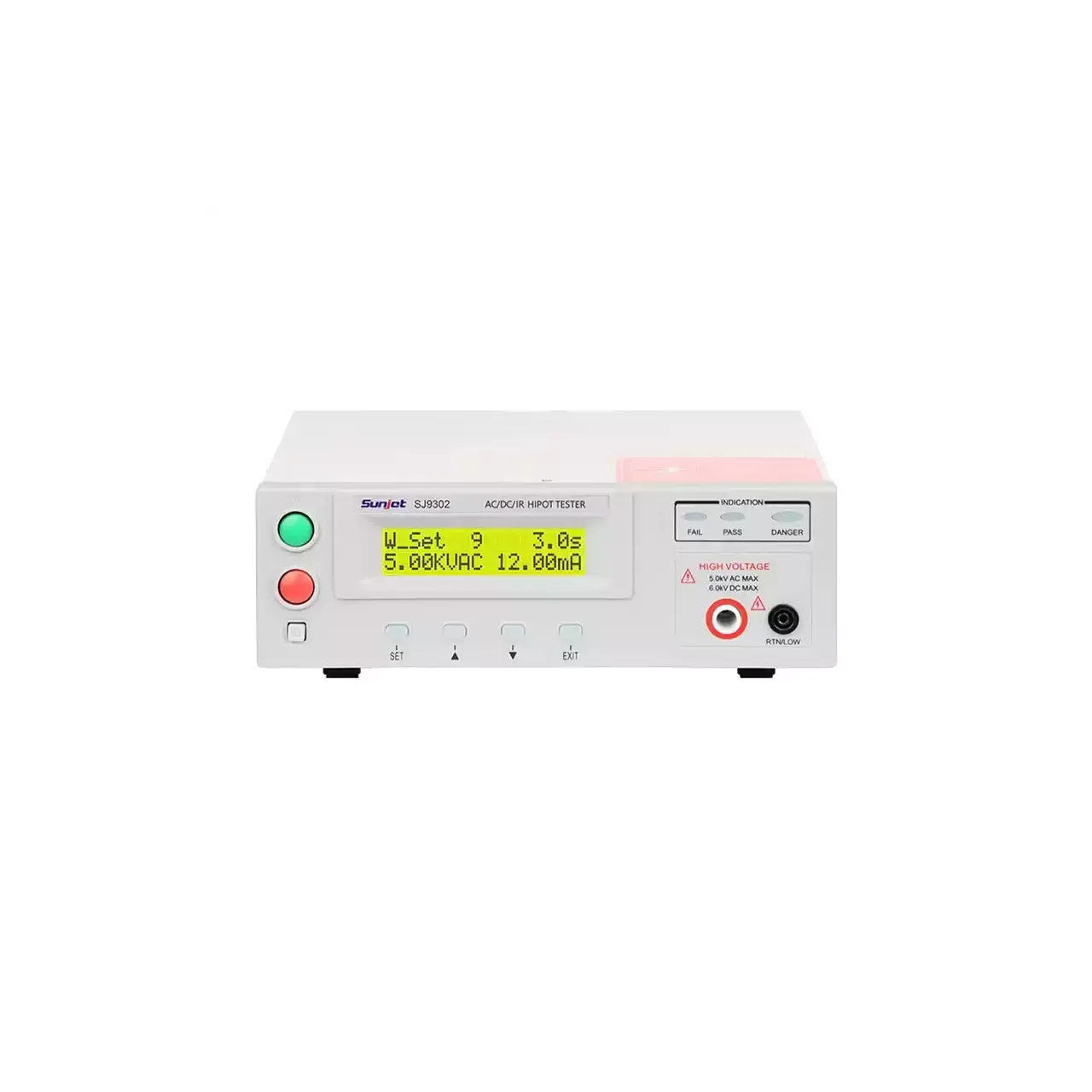
Programmable withstand voltage and insulation tester shown from the front, with the two-line backlit LCD at the top left, the function keys below it and the high-voltage output terminals along the lower edge

SJ7110 (6 models) · Electrical Safety Testers

Programmable Withstand Voltage and Insulation Tester

Programmable safety tester range applying up to 5 kV AC or 6 kV DC, measuring leakage current against preset limits and insulation resistance to 50 GΩ, with arc detection and ten memory groups.

AC output
0.10 kV to 5.00 kV
DC output
0.10 kV to 6.00 kV, on five of the six models
Leakage current
0 to 12.00 mA AC and 0 to 5.00 mA DC as standard; 20 mA and 10 mA on the largest model
Insulation resistance
1 MΩ to 10 GΩ on the mid range; 0.1 MΩ to 50.0 GΩ on the two largest models
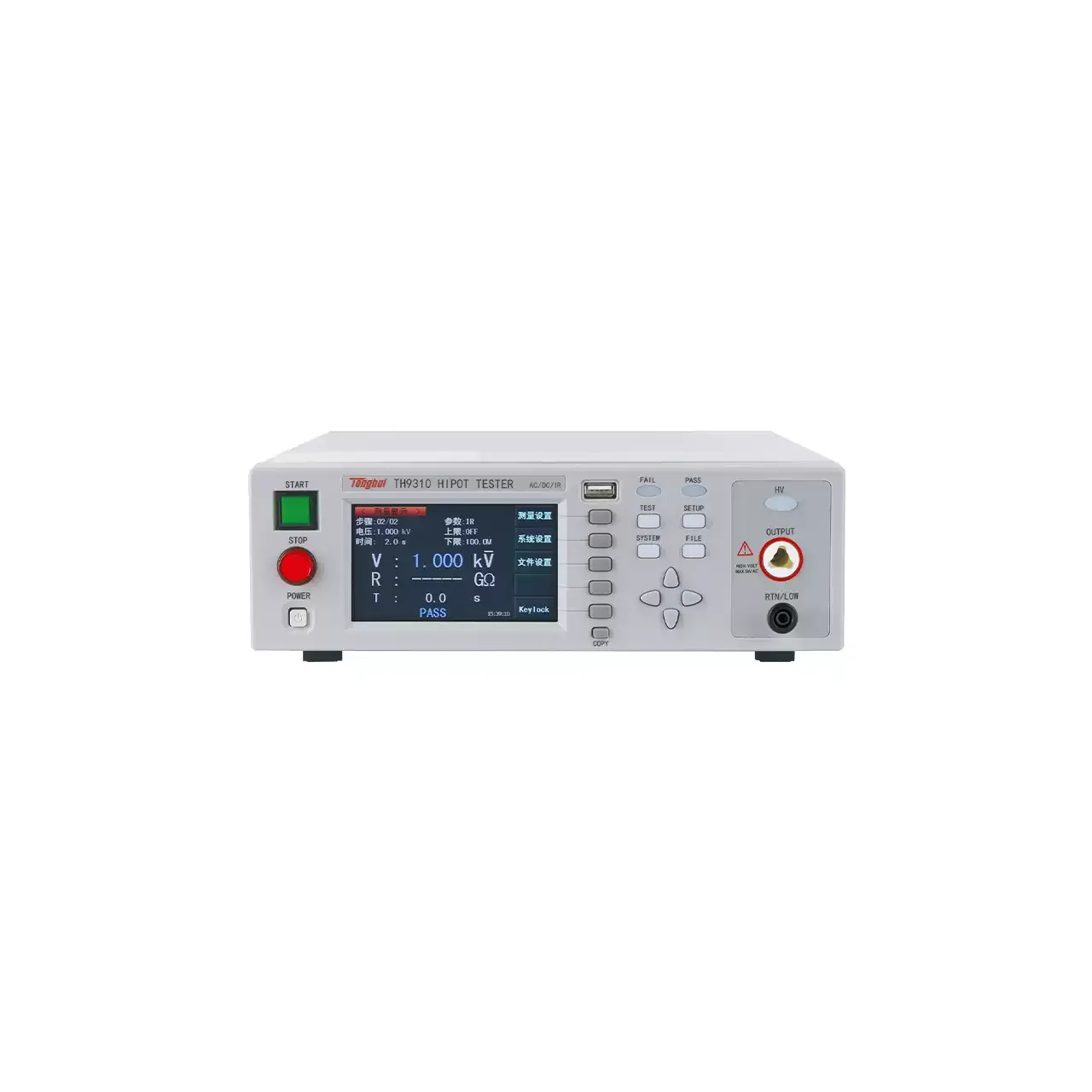
Programmable withstand voltage tester with a colour TFT display on the left of the front panel, a column of function keys beside it and the high-voltage output terminals below

TH9310 (6 models) · Electrical Safety Testers

TFT Display AC/DC Withstand Voltage and Insulation Tester

Programmable safety tester with a 480 by 272 TFT display, AC and DC withstand voltage to 6 kV, insulation resistance to 10 GΩ, twenty test files of twenty steps and arc detection.

AC output
0.05 kV to 5.00 kV, ±2%
DC output
0.05 kV to 6.00 kV, ±2%, on four of the six models
AC leakage current
0 to 10.00 mA; 1 µA to 20.00 mA on the higher-current model
Insulation resistance
0.1 MΩ to 10.0 GΩ at 0.10 kV to 1.00 kV

Request a quotation for the 7305

Send the configuration you need and we will confirm availability, lead time and terms. Minimum order quantity is 1 pc.

Request for quotation

Request a quotation - 7305

Send the technical detail and we will confirm availability, lead time and terms. In-stock items ship within 48 hours; customized specifications typically take 2-10 days. Minimum order quantity is 1 pc.

The more of this you can give us, the fewer exchanges are needed before we can quote.
No file chosen
Datasheet, drawing, BOM or photograph. One file, up to 10 MB (PDF, Office, image or ZIP).

By submitting this form you agree that we may contact you about this enquiry. We do not sell or share enquiry data. See our privacy policy.

Items held in stock are dispatched within 48 hours of order confirmation. Customized specifications are produced to order and typically ship within 2 to 10 days. Transit time then depends on the shipping method and destination.

Request a Quote WhatsApp