- AC output
- 0 to 5.00 kV, 12 mA
- DC output
- 0 to 6.00 kV, 5 mA, on four of the eight models
- Frequency
- 50 or 60 Hz, selectable
- Leakage limits
- 0.10 to 12.00 mA AC and 0.02 to 5.00 mA DC, upper and lower set independently
- Insulation resistance
- 1 MΩ to 9999 MΩ at 0.1 to 1.00 kV DC
- Program memory
- Five groups on the compact models; ten groups of three steps on the large-output models
- Arc detection
- Nine sensitivity levels, with level zero switching it off
- Display
- 16 character by 2 line LCD
- Remote control
- Nine-pin PLC interface, with several instruments synchronised
- Body
- 280 × 89 × 300 mm, 8.5 kg
A safety tester is often the last instrument bought for a bench and the first one blamed when a product fails in the field. The useful question is not how much voltage it can produce but whether it can run the same test, in the same order, every time. This range is built for that, in two body sizes.
Product overview
Eight models share one test engine. The differences are which tests are fitted and how much current the output can deliver: four compact models at 12 mA and four large-output models at 20 mA, each available as AC only, AC with insulation, AC and DC, or all three.
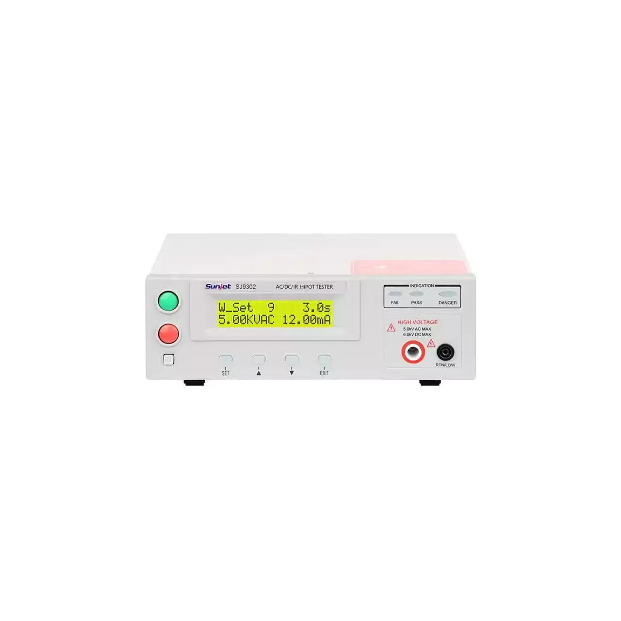
The compact body is 280 mm wide and 8.5 kg, which is small enough to sit on a bench beside the fixture rather than under it. The front panel carries a two-line character display, the function keys and the test terminals; the rear carries the PLC connector, the mains selector and the calibration button.
How the tester works
The instrument generates a sine wave at a selected frequency, steps it up to the programmed voltage over a rise time, and holds it for the test time. Throughout the hold it measures the current flowing through the item and compares it with two limits. Exceeding the upper limit means the insulation broke down; dropping below the lower limit usually means the lead is not connected, which is why both are set rather than only one.
For a direct test the output is rectified and smoothed, and the ripple figure is quoted at full load because that is where it is worst. Insulation resistance is measured at a lower direct voltage, with the reading taken after a settling period, since the current through good insulation takes time to stop falling.
Arc detection watches the current for the fast step that a local flashover produces. The nine sensitivity levels exist because a fixture with long leads is noisier than a short one, and a detector set too sensitively trips on the fixture rather than on the product.
How to select the right model
The first question is which tests the product standard requires. An AC withstand test alone points at 7110 or 7130; adding a direct test brings in 7120 or 7140; adding insulation brings in 7112, 7122, 7132 or 7142.
The second is current. Twelve milliamps covers small appliances and electronic assemblies; twenty milliamps is for items that draw more leakage, and it is the only reason to move to the larger body. The third is program count: five groups on the compact models suits a bench that runs a handful of products, while ten groups of three steps suits a line that changes over more often or runs a sequence.
Input voltage selection matters if the instrument will travel. The same unit can be set for 115 or 230 V, which is unusual at this size and saves a transformer on site.
Measurement limitations and selection considerations
The alternating output is a sine wave at a fixed frequency, so the test is comparable with a standard written for that frequency and not with a high-frequency or impulse test. Products whose insulation is specified under a different waveform need a different instrument.
Leakage current is measured as the total flowing through the item, which includes the current through the fixture and the leads. On a product with very low leakage, that fixture current can be a large fraction of the reading, which is why the lower limit has to be set with the fixture connected and characterised.
Finally, the instrument holds a voltage for a time; it does not follow a ramp to breakdown. Where the breakdown voltage itself is the quantity of interest, a tester with a programmable ramp and a recorded curve is the right instrument, and a pass or fail unit will only report that breakdown happened somewhere above the limit.
Every value below is taken from source documentation. Where a parameter is not stated in the available material it is marked as information required rather than estimated.