- AC output
- 0.05 kV to 5.00 kV, ±2%
- DC output
- 0.05 kV to 6.00 kV, ±2%, on four of the six models
- AC leakage current
- 0 to 10.00 mA; 1 µA to 20.00 mA on the higher-current model
- Insulation resistance
- 0.1 MΩ to 10.0 GΩ at 0.10 kV to 1.00 kV
- Test files
- Twenty files of twenty steps, each step free to use any test mode
- Arc detection
- 1 mA to 20 mA
- Display
- 480 by 272 dot matrix TFT LCD
- Interface
- RS232, USB device, USB host, HANDLER and PLC
- Safety cut-off
- Output is removed when the current measured at the high-voltage terminals indicates contact with an operator
- Timing
- Rise and fall 0.1 s to 999.9 s; test 0.2 s to 999.9 s
A production safety test is a sequence, not a single measurement, and the instrument that runs it has to hold the sequence as a program. This series is built around that: twenty files, twenty steps each, with any test mode available at any step.
Product overview
The range covers AC withstand, DC withstand and insulation resistance in one instrument, with the combination fixed by the model. The two standard models carry all three functions and differ in current range; the AC-only model exists for tests that need nothing else; and the two TH9301 variants keep an older numbering that the material still carries.
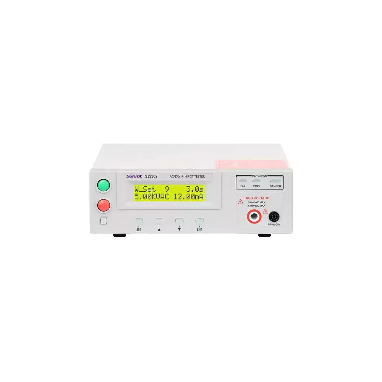
The front panel is a 480 by 272 dot matrix display with a column of function keys beside it. That is the part that changes how the instrument is used: a two-line character display shows one value at a time, while this one shows the step, the measured value and the limits together, which is what a multi-step recipe needs when it is being checked rather than merely run.
How the tester works
The instrument raises its output to the programmed voltage over a set rise time, holds it for the test time, and compares the resulting leakage current with an upper and a lower limit. The lower limit matters as much as the upper one: a reading that falls below it usually means the test lead is not connected, and a one-sided limit would pass that silently.
The insulation resistance test uses a lower direct voltage and a longer settling time, because the current through good insulation is very small and takes time to stabilise. The material gives a waiting time of 0.2 to 999.9 seconds for that reason. Accuracy is quoted in two segments, tighter below 1 GΩ and wider above it, which is the usual shape for this measurement.
Contact protection runs throughout. If the current at the high-voltage terminals takes the value that a person touching them would produce, the output is cut. It is a second line of defence behind the interlock and the warning lamps.
How to select the right model
Start from the product standard: it fixes the test voltage, the leakage current limit and whether insulation resistance is part of the test. That last point settles the model family immediately, since the AC-only versions cannot run an insulation test at all.
The second question is current range. The 10 mA version covers most small appliances and electronic assemblies; the 20 mA version exists for items that draw more leakage, and it also resolves the bottom of the range more finely, which matters when a limit is set in microamps.
The third is how the item is contacted. A single-point test can use the front terminals and a probe; a product with several test points in sequence needs the four- or eight-channel scanner version, which the material lists as a separate model rather than an accessory.
Measurement limitations and selection considerations
The result is a judgement at one voltage for one period. It does not predict how insulation behaves after a thousand hours at temperature, and it does not replace a type test. A routine production test is a check that the item is the same as the one that passed the type test, and the instrument is chosen for repeatability at that check rather than for range.
The leakage current ranges set the smallest item this instrument can test meaningfully. An assembly whose normal leakage is a few microamps sits near the bottom of the range, where the resolution of the instrument rather than the item dominates the reading.
Finally, the recipe is part of the measurement. A test that passes on the bench with a hand-held probe can fail on a fixture whose own leakage and capacitance are higher than the limit being applied, so the fixture has to be characterised before the limits are set.
Every value below is taken from source documentation. Where a parameter is not stated in the available material it is marked as information required rather than estimated.