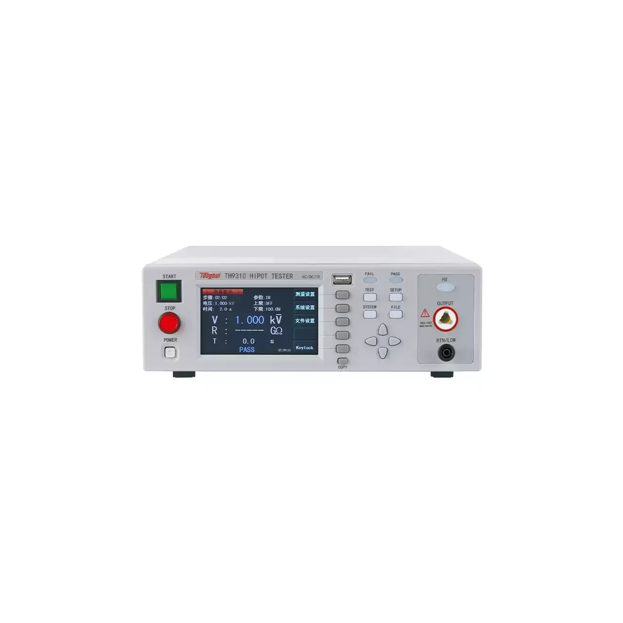
Electrical Test & Measurement · Electrical Safety Testers

Four-in-One Electrical Safety Compliance Tester

Bench safety compliance analyser combining AC and DC withstand, insulation resistance and, on the top model, ground bond testing, with stored programs and a matrix scanner interface.

7440 (4 models) ·

Key specifications

AC withstand
0 to 5 kV, up to 40 mA
DC withstand
0 to 6 kV, up to 9999 μA
Insulation resistance
100 to 1000 V DC, 1 to 9999 MΩ
Ground bond
3 to 40 A, 0 to 600 mΩ, on 7440 only
Program memory
50 groups of eight steps
Display
20 × 2 cm dot matrix OLED
Arc detection
Nine sensitivity levels
Scanner
One matrix scanner built in, one more connectable; H.V × 4 and H.V × 8 optional
Interface
PLC test and reset inputs, pass, fail and processing outputs, RS232
Body
432 × 147 × 500 mm and 22 kg on the drawing for 7440

A single safety analyser is bought for a reason that is rarely written on a specification sheet: the product under test should not have to be unplugged, moved and re-connected between three instruments. The value of a combined unit is the sequence it can run without an operator in the middle of it.

Product overview

Four models sit in one body. The top model runs an alternating withstand test, a direct withstand test, an insulation resistance test and a ground bond test. The other three drop the bond output and keep the rest, and two of them cap the alternating leakage current at a lower figure than the other two.

The controls are arranged for sequence entry rather than for a single measurement: function keys down the left of the keypad select the test, a numeric block enters the values, and the display shows the step, the setpoint and the measured value together. The rear panel carries the high voltage output, the scanner connections, a serial port, the remote control connector and an input for a barcode reader.

How the compliance tester works

Each function applies a quantity and judges the response. In the alternating withstand test a sine wave is raised over a programmed rise time to the set voltage and held for the test time, while the current through the item is compared with an upper and a lower limit. Exceeding the upper limit is a breakdown; falling below the lower limit usually means the item is not connected. The direct test does the same with a rectified output, and the ripple figure is quoted at full load because that is where it is worst.

Insulation resistance is measured at a lower direct voltage, and the reading is taken after a delay because the current through good insulation keeps falling for a while after the voltage is applied. The material specifies the accuracy in two bands, above and below the middle of the voltage range, which reflects that behaviour rather than a change in the instrument.

The bond test is a different measurement in the same box. A low alternating voltage drives a heavy current through the protective conductor, the drop across it is measured, and the resistance is derived and compared with limits that change with the current segment. A zeroing step removes the resistance of the leads first, which matters because on a bond of a few milliohms the leads can be the larger part of the reading.

How to select the right configuration

The first question is whether a bond test is required at all. It is the only function that separates the top model from the rest, and it cannot be added later, so a product standard that calls for it decides the model outright.

The second is the leakage ceiling. Two models stop at the lower figure and two reach the higher one, and the figure has to come from the product standard rather than from a preference for headroom.

The third is the fixture. A product with several test points is impractical to test one lead at a time, and the scanner interface is what turns the instrument into a sequencer. Count the points before choosing the scanner, and remember that one scanner is already inside the instrument.

The fourth is how programs are recalled. Fifty groups with a name stored against each is enough for a varied bench, but if operators select by product label, the barcode input at the rear is the feature that decides the configuration.

Measurement limitations and selection considerations

The instrument judges against limits; it does not characterise insulation. Where the breakdown voltage itself is the quantity of interest, a tester with a ramped output and a recorded curve is the right instrument, and a pass or fail unit will only report that breakdown happened somewhere above the limit.

Leakage measurement includes everything connected across the output, including the fixture, the scanner and the leads. On a product with very low leakage that residual current can be a large fraction of the reading, which is why the lower limit has to be set with the fixture in place and characterised, not on an open bench.

The bond function belongs to one model only, and its current is capped at a figure that may be below what a particular standard asks for. The material mentions a higher current on request, which means the requirement has to be raised at the order stage rather than assumed from the model table.

Finally, combining functions in one box means one failure stops the sequence. That is usually what a production test wants, but a laboratory that needs to investigate which test failed, and by how much, may prefer separate instruments with independent records.

Features

  • Four test functions share one test sequence, so a product can be run through withstand, insulation and bond without moving it between instruments
  • The ground bond function is confined to the top model, which is what separates it from the other three
  • Fifty program groups of eight steps each, with a name stored against every group so a product can be recalled rather than re-entered
  • A matrix scanner interface expands one instrument across multiple test points; one scanner is built in and a second can be added
  • Arc detection is adjustable over nine levels, so the threshold can be raised on a noisy fixture instead of being switched off
  • The keyboard is locked with a numeric password, which keeps the stored programs intact on a shared bench
  • Display brightness and buzzer volume are both adjustable, for a bench that is either brightly lit or kept quiet
  • A barcode scanner can be connected at the rear, so a program can be selected from the product label rather than from a list

Technical specifications

Every value below is taken from source documentation. Where a parameter is not stated in the available material it is marked as information required rather than estimated.
AC withstand
Output voltage0 to 5 kV, resolution 1 V, ±(1% of setting + 5 V)Standard
Output frequency50 or 60 Hz, selectable, ±100 ppmStandard
Regulation±(1% of setting + 5 V) from no load to full loadStandard
WaveformSine, total harmonic distortion below 2% into a resistive load, crest factor 1.3 to 1.5Standard
Upper leakage limit0.00 to 40.00 mA on 7440 and 7430; 0.00 to 30.00 mA on 7420 and 7410; ±(2% of setting + 3 counts)Standard
Lower leakage limit0.000 to 9.999 mA, resolution 0.001 mA, ±(2% of setting + 3 counts)Standard
Rise time0.1 to 999.9 s, resolution 0.1 s, ±(0.1% + 0.05 s)Standard
Test time0.3 to 999.9 s (0 = continuous), resolution 0.1 s, ±(0.1% + 0.05 s)Standard
Arc detection1 to 9, with 9 the highest sensitivityStandard
Test lead zeroing0 to 200 mA, manual or automatic, as printedStandard
DC withstand
Voltage display range0.00 to 6.00 kV, resolution 1 V, ±(2% of setting + 5 V)Standard
RippleBelow 5%, measured at 6 kV into a 9999 μA resistive loadStandard
Upper leakage limit0.000 to 9999 μA, resolution 0.1 μA, ±(2% of setting + 3 counts)Standard
Lower leakage limit0.0 to 9999 μA, resolution 0.1 μA, ±(2% of setting + 3 counts)Standard
Rise time0.1 to 999.9 s, resolution 0.1 s, ±(0.1% + 0.05 s)Standard
Test time0.4 to 999.9 s (0 = continuous), resolution 0.1 s, ±(0.1% + 0.05 s)Standard
Arc detection1 to 9, with 9 the highest sensitivityStandard
Insulation resistance
Output voltage100 to 1000 V DC, resolution 1 V, ±(1% of setting + 3 V)Standard
Resistance resolution1 MΩStandard
Accuracy at 500 to 1000 V, 1 to 1000 MΩ±(2% of setting + 2 counts)Standard
Accuracy at 500 to 1000 V, 1000 to 9999 MΩ±(8% of setting + 2 counts)Standard
Accuracy at 100 to 500 V, 1 to 1000 MΩ±(8% of setting + 2 counts)Standard
Upper limit0 to 9999 MΩ, where 0 switches the judgement offStandard
Lower limit1 to 9999 MΩStandard
Judgement delay0.5 to 999.9 s (0 = continuous judging), resolution 0.1 sStandard
Charging current lower limit0.000 to 3.500 μA, or set automaticallyStandard
Ground bond, 7440 only
Output voltage3 to 8 V AC, resolution 0.01 V, ±(2% of reading + 3 counts) measured open circuitStandard
Output frequency50 or 60 Hz, selectable, ±100 ppmStandard
Output current3.00 to 30 A AC, 0.01 A steps, ±(2% of setting + 3 counts); 40 A on requestStandard
Resistance range0 to 600 mΩ, resolution 1 mΩ, ±(2% of setting + 2 counts)Standard
Upper and lower limits0 to 600 mΩ over 3 to 10 A; 0 to 150 mΩ over 15 to 30 A; resolution 1 mΩStandard
Test time0.5 to 999.9 s (0 = continuous), resolution 0.1 s, ±(0.1% + 0.05 s)Standard
Lead zero compensation200 mΩ maximum, resolution 1 mΩ, ±(1% of setting + 1 mΩ)Standard
Control, memory and interface
Program memory50 groups, each with eight steps, each group named for a productStandard
Display20 × 2 cm dot matrix OLEDStandard
Display brightnessNine steps, set from the keypadStandard
Buzzer volumeTen steps, where 0 switches it offStandard
Keyboard lockFour-digit numeric passwordStandard
Remote inputTest and resetStandard
Remote outputPass, fail and processingStandard
Serial interfaceRS232Standard
Matrix scannerOne built in; two scanners in total can be connectedStandard
Optional scannersH.V × 4 and H.V × 8Optional
CalibrationSoftware calibration entered from the panel keysStandard
Supply, body and environment
Input supply115 or 230 V AC ±15%, single phase, selectableStandard
Input frequency47 to 63 HzStandard
Input fuse6.3 A as printed, with a 5.0 A figure also visible on the drawingStandard
Dimensions432 × 147 × 500 mm and 432 × 147 × 300 mm, not bound to individual modelsStandard
Weight22 kg, 22 kg, 18 kg and 12 kg listed without a model allocationStandard
Operating environment0 to 40 °C, 20 to 80% RHStandard
Standard accessoryInsulation test lead, listed for the 74 seriesStandard
Calibration certificateNot stated in the materialInformation required
Ingress protectionNot stated in the materialInformation required

Available models

Selection table
Model Configuration Key ranges Availability
7440 AC and DC withstand, insulation and ground bond AC to 40 mA, DC to 9999 μA, insulation to 9999 MΩ, bond to 600 mΩ The only model with the ground bond function
7430 AC and DC withstand with insulation AC to 40 mA, DC to 9999 μA, insulation to 9999 MΩ No ground bond function
7420 AC and DC withstand with insulation AC to 30 mA, DC to 9999 μA, insulation to 9999 MΩ Lower AC leakage ceiling than 7430
7410 AC and DC withstand with insulation AC to 30 mA, DC to 9999 μA, insulation to 9999 MΩ Listed with the same figures as 7420

Customization

  • A second matrix scanner, in H.V × 4 or H.V × 8 form, for a fixture with more test points
  • Ground bond output raised to 40 A on request

Certification and compliance

Certification documents not yet supplied

Certifications are only published once a certificate copy can be produced, so this section is deliberately empty rather than populated with assumed approvals. Tell us which approvals your application requires and we will confirm what is available for this instrument.

Parameters still to be confirmed

The following are required for a complete specification but are not stated in the documentation supplied to us. They are listed rather than estimated:

  • Which dimensions and weight belong to each of the four models, since two body sizes and four weights are listed without a model allocation
  • Whether a six-in-one version with power and low-voltage start testing exists, since the overview describes it but no model or specification for it appears anywhere in the material
  • What separates 7420 from 7410, which carry identical figures in every column of the model table
  • Whether the ground bond output is 30 A as given in the detailed table or 40 A as given in the model table, and what the 40 A option changes
  • The correct input fuse rating, given as 6.3 A in the table and 5.0 A in a watermark on the same drawing
  • Whether the test lead zeroing row of the withstand tables, printed as 0 to 200 mA, is a current or a resistance setting
  • Calibration certificate availability and the standard it would be issued against
  • Warranty period and its terms
  • The length and rating of the insulation test lead
  • Duty cycle for repeated bond tests at the top of the current range
  • Ingress protection rating, which the material does not give

Frequently asked questions

Do I need the model with the ground bond function?

Only if the product has a protective conductor that has to be checked for continuity at a defined current. The other three models run the withstand and insulation tests but have no bond output at all, so a bond test would have to be done on a separate instrument. If the product standard calls for a bond test, the choice is made for you.

What is the difference between 7420 and 7410?

The material gives them the same figures in every column, including the alternating leakage ceiling, and does not explain the distinction. Treat the two as the same specification until the supplier confirms what separates them, and specify by the figure your standard requires rather than by model number alone.

Can one instrument test several points on the same product?

Yes, through the matrix scanner. One scanner is built into the instrument and a second can be connected, and the scanners are offered in four-channel and eight-channel form. The instrument steps through the points in the stored sequence, which is what makes a multi-point harness practical on a single bench.

What has to be confirmed before a quotation?

Whether a bond test is required, which decides between the top model and the others; the leakage ceiling the product standard allows; how many test points the fixture has, which sets the scanner requirement; and whether programs have to be selected from a barcode, since that needs the scanner interface at the rear.

Related products

Other models in the same range

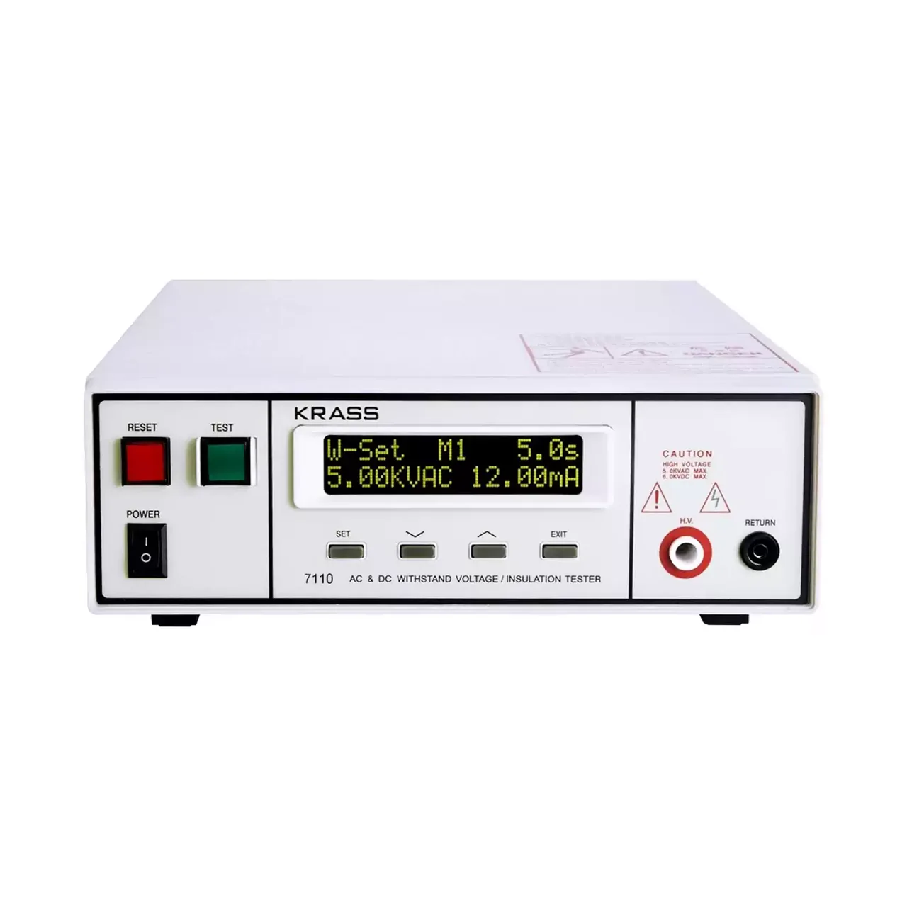
Compact programmable safety tester shown from the front with the two-line LCD at the upper left, a row of function keys beneath it and the test terminals along the lower right

7110 (8 models) · Electrical Safety Testers

Compact AC/DC Withstand Voltage and Insulation Tester

Compact programmable safety tester with 5 kV AC and 6 kV DC withstand voltage, insulation resistance to 9999 MΩ, five stored programs and PLC remote control.

AC output
0 to 5.00 kV, 12 mA
DC output
0 to 6.00 kV, 5 mA, on four of the eight models
Frequency
50 or 60 Hz, selectable
Leakage limits
0.10 to 12.00 mA AC and 0.02 to 5.00 mA DC, upper and lower set independently
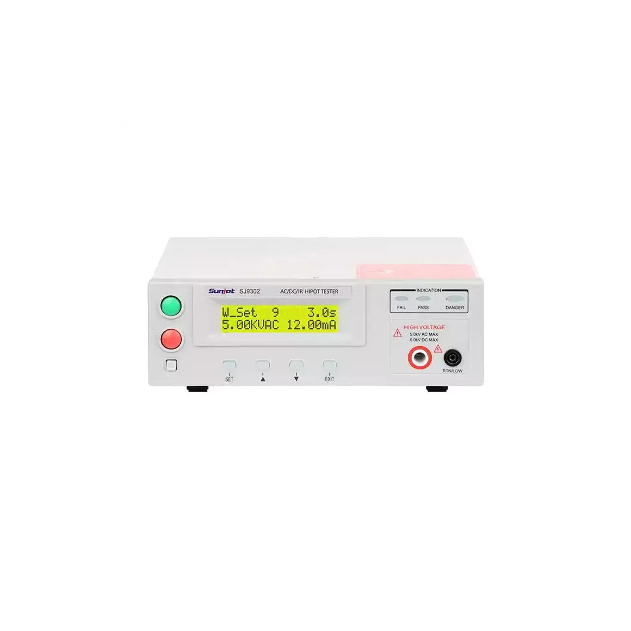
Programmable withstand voltage and insulation tester shown from the front, with the two-line backlit LCD at the top left, the function keys below it and the high-voltage output terminals along the lower edge

SJ7110 (6 models) · Electrical Safety Testers

Programmable Withstand Voltage and Insulation Tester

Programmable safety tester range applying up to 5 kV AC or 6 kV DC, measuring leakage current against preset limits and insulation resistance to 50 GΩ, with arc detection and ten memory groups.

AC output
0.10 kV to 5.00 kV
DC output
0.10 kV to 6.00 kV, on five of the six models
Leakage current
0 to 12.00 mA AC and 0 to 5.00 mA DC as standard; 20 mA and 10 mA on the largest model
Insulation resistance
1 MΩ to 10 GΩ on the mid range; 0.1 MΩ to 50.0 GΩ on the two largest models
Programmable withstand voltage tester with a colour TFT display on the left of the front panel, a column of function keys beside it and the high-voltage output terminals below

TH9310 (6 models) · Electrical Safety Testers

TFT Display AC/DC Withstand Voltage and Insulation Tester

Programmable safety tester with a 480 by 272 TFT display, AC and DC withstand voltage to 6 kV, insulation resistance to 10 GΩ, twenty test files of twenty steps and arc detection.

AC output
0.05 kV to 5.00 kV, ±2%
DC output
0.05 kV to 6.00 kV, ±2%, on four of the six models
AC leakage current
0 to 10.00 mA; 1 µA to 20.00 mA on the higher-current model
Insulation resistance
0.1 MΩ to 10.0 GΩ at 0.10 kV to 1.00 kV

Request a quotation for the 7440

Send the configuration you need and we will confirm availability, lead time and terms. Minimum order quantity is 1 pc.

Request for quotation

Request a quotation - 7440

Send the technical detail and we will confirm availability, lead time and terms. In-stock items ship within 48 hours; customized specifications typically take 2-10 days. Minimum order quantity is 1 pc.

The more of this you can give us, the fewer exchanges are needed before we can quote.
No file chosen
Datasheet, drawing, BOM or photograph. One file, up to 10 MB (PDF, Office, image or ZIP).

By submitting this form you agree that we may contact you about this enquiry. We do not sell or share enquiry data. See our privacy policy.

Items held in stock are dispatched within 48 hours of order confirmation. Customized specifications are produced to order and typically ship within 2 to 10 days. Transit time then depends on the shipping method and destination.

Request a Quote WhatsApp