Electrical Test & Measurement · LCR Meters

Transformer Comprehensive Tester

Four transformer testers with 20-channel scanning, LCR and DC resistance measurement at 0.05% basic accuracy, built-in DC bias and test frequencies from 20 Hz to 1 MHz for production testing of wound components.

HG7729 (4 models) ·

Key specifications

Test frequency
20 Hz to 200 kHz on HG7729; 20 Hz to 300 kHz on HG7729A and HG7729B; 20 Hz to 1 MHz on HG7729C
Scanning
20-channel transformer scan on all four models
LCR parameters
|Z|, |Y|, C, L, X, B, R, G, D, Q and phase, plus DC resistance, turns and phase
Transformer scan parameters
Turns ratio, number of turns, phase, inductance, capacitance, leakage inductance, quality factor, AC resistance, DC resistance, balance, pin short and LED
Basic accuracy
0.05% for LCR and DC resistance; 0.1% for turns ratio
Signal level
5 mV to 2 V for LCR tests, 5 mV to 10 V for the turns test, and 5 mV to 10 V as an option for LCR; automatic level 5 mV to 1 V
DC bias
Built in, ±5 V or ±50 mA, accuracy 1%
Speed and storage
75, 20 or 6 measurements per second at 10 kHz and above; 100 setups inside and 500 on a USB drive
Interface
RS232C, USB TMC, USB CDC, HANDLER and GPIB, all supplied as standard
Body
280 × 88 × 320 mm and 4.0 kg in the size drawing; 400 × 132 × 350 mm and about 10 kg in the parameter table

A transformer is not one component but a set of coupled windings, and the parameters that decide whether it works are spread across them: ratio, inductance, leakage, capacitance between windings and the resistance of each coil. Testing them one at a time is what a comprehensive tester is built to avoid.

Product overview

The range contains four instruments that share a 20-channel scanner, a full LCR engine and a transformer parameter set. What separates them is the frequency ceiling, which runs from 200 kHz in the base model to 1 MHz in the top one.

Everything else is common: the same accuracy for impedance and for turns ratio, the same built-in bias source, the same display and the same interfaces. That makes the choice simpler than the model count suggests, and it also means the frequency is the only real decision unless the fixture or the line imposes another.

How the transformer tester works

The instrument drives one winding with a signal at a chosen frequency and measures the voltage and current at the terminals of that winding and of the others. From the ratios between them it derives the turns ratio and the phase relationship, and from the impedance it derives inductance, leakage inductance, capacitance and the loss terms.

The scanner is what makes this practical. It connects the instrument to the pins in a fixed sequence, so a transformer with several windings is measured in one pass. Each measurement is compared against a limit, and the instrument reports which bin the part belongs to.

The built-in bias source matters for the inductance reading. A magnetic core behaves differently depending on where it sits on its magnetisation curve, and a small-signal inductance measured without bias can be far from the value the circuit sees. Applying the bias current or voltage brings the core to the operating point before the measurement is taken.

The measurement is defined by its frequency and its level. Both are set per test, and both appear in the result, because an inductance quoted without them is not a specification of anything.

How to select the right transformer tester

Start with the highest frequency at which any parameter has to be measured. That single figure separates the range: a part specified at a few hundred kilohertz at most fits the lower models, while a part with a specification at or near a megahertz needs the top one.

Then look at the parameters. If the test is a turns ratio and a winding resistance, the basic set is enough. If the part is characterised for leakage inductance, inter-winding capacitance, balance and pin continuity, the full scan set is what the fixture and the program have to cover, and the fixture becomes as important as the instrument.

Then consider the bias. A transformer whose inductance is specified at a DC bias cannot be checked without one, and the built-in source removes the external supply that would otherwise have to be wired into the fixture.

Then look at the line. The scan channels, the bin count and the handler interface decide how the part is presented and sorted; the serial, USB and bus interfaces decide who reads the result. Send the transformer drawing, the pin list, the parameters and the frequency at which each is specified, and a model, a scanner and a fixture can be quoted against them.

Measurement limitations and selection considerations

The instrument measures at its terminals, so the fixture is inside the measurement. Lead length, contact resistance and the capacitance of the scanner add to the values being read, and a fixture built for one transformer rarely suits another without correction.

The bias source has a limited range, and a part that needs more bias than the source can supply will be measured off its operating point. The material gives the range of the built-in source, and that range should be compared with the application before the instrument is chosen.

The frequency ceiling is a hard limit. A parameter specified above it cannot be measured on that model at all, and measuring at a lower frequency instead produces a different number rather than an approximation of the right one.

Finally, the accuracy figures apply under conditions the material does not state. The warm-up time and the calibration state are part of the measurement, and a comparison between instruments or between shifts is only meaningful when both are held to the same conditions.

Features

  • Twenty-channel scanning, so a transformer with several windings and a set of pins is measured in one pass rather than one connection at a time
  • Transformer parameters and LCR parameters on one instrument, which removes the second bench and the second handling of the part
  • Turns ratio accuracy quoted separately from the impedance accuracy, because the two are different measurements and mixing the figures overstates one of them
  • A built-in DC bias source, so inductance can be measured with the core driven to the operating point the application uses
  • Ten-bin sorting with bin counting, which allows a production run to be graded and counted without a separate station
  • Ten measurements per second in the medium speed setting and seventy-five in the fast one, at 10 kHz and above, so the instrument can keep up with a handler
  • WIFI module available as an option, for a line where pulling a cable to each bench is the obstacle
  • RS232C, both USB modes, HANDLER and GPIB fitted as standard, so the instrument fits an existing controller without an option card

Technical specifications

Every value below is taken from source documentation. Where a parameter is not stated in the available material it is marked as information required rather than estimated.
Test parameters
Impedance parameters|Z|, |Y|, C, L, X, B, R, G, D, Q and phase angle, with DC resistance, turns and phaseStandard
Transformer scan parametersTurns ratio, number of turns, phase, inductance, capacitance, leakage inductance, quality factor, AC resistance, DC resistance, balance, pin short and LEDStandard
Scan channels20Standard
Equivalent circuitSeries or parallelStandard
Range modeAutomatic, hold or manual selectionStandard
Display ranges
Impedance, resistance and reactance0.00001 Ω to 99.9999 MΩStandard
Admittance, conductance and susceptance0.00001 nS to 99.9999 SStandard
Capacitance0.00001 pF to 9.9999 FStandard
Inductance0.00001 µH to 99.9999 kH, printed with the kilo prefix as in the materialStandard
Dissipation factor0.00001 to 9.99999Standard
Quality factor0.00001 to 99999.9Standard
Phase angle−179.999° to 179.999°, or −3.14159 to 3.14159 radStandard
Deviation−999.999% to 999.999%Standard
DC resistance0.00001 Ω to 99.9999 MΩStandard
Signal and accuracy
Test frequency, HG772920 Hz to 200 kHzStandard
Test frequency, HG7729A and HG7729B20 Hz to 300 kHz on bothStandard
Test frequency, HG7729C20 Hz to 1 MHzStandard
LCR signal level5 mV to 2 V; 5 mV to 10 V with the optional level rangeStandard
Turns test signal level5 mV to 10 VStandard
Automatic level5 mV to 1 V, accuracy 5%, resolution 1 mVStandard
Basic accuracyLCR and DC resistance 0.05%; turns ratio 0.1%Standard
Output and input impedance10 Ω and 25 Ω, 50 Ω, or 100 Ω, selectableStandard
DC biasBuilt in, ±5 V or ±50 mA, accuracy 1%Standard
Accuracy conditionsThe material does not state the warm-up time or the calibration conditions for the quoted accuracyInformation required
Speed and control
Measurement speed75 per second fast, 20 medium and 6 slow, stated for 10 kHz and aboveStandard
Speed below 10 kHzNot stated in the materialInformation required
Trigger modesInternal, manual, external and busStandard
Delay time0 to 60 s in 1 ms stepsStandard
ComparatorTen bins with bin countingStandard
Display, storage and interface
Display7-inch 16:9 TFT LCD, 800 × 480Standard
Internal storage100 setupsStandard
USB storage500 files on a USB drive, saved and recalledStandard
Standard interfacesRS232C, USB TMC, USB CDC, HANDLER and GPIBStandard
USB hostFor USB drive storage and recallStandard
Optional moduleWIFI moduleOptional
Rear panelScanner, RS-232C and barcode connectors, mains inletStandard
Power and mechanical
Mains supply220 V ±10%, 50 Hz or 60 Hz ±5%Standard
Operating temperature0 °C to 40 °CStandard
Operating humidityBelow 90% relative humidityStandard
Dimensions, size drawing280 mm wide × 88 mm high × 320 mm deepStandard
Weight, size drawing4.0 kgStandard
Dimensions, parameter table400 mm wide × 132 mm high × 350 mm deepStandard
Weight, parameter tableAbout 10 kgStandard
Supplied accessoryFoot switch, listed for all four modelsStandard
Full packing listNot stated in the materialInformation required

Available models

Selection table
Model Configuration Key ranges Availability
HG7729 20 Hz to 200 kHz, 20-channel scan, 0.05% LCR accuracy Signal level 5 mV to 1 V in the model table; 20-channel transformer scan The base model, for parts tested below 200 kHz
HG7729A 20 Hz to 300 kHz, 20-channel scan Same accuracy and level as the base model, with the higher frequency ceiling For parts specified between 200 kHz and 300 kHz
HG7729B 20 Hz to 300 kHz, 20-channel scan The frequency range printed for this model is the same as for HG7729A The material gives no difference between this model and HG7729A beyond the designation
HG7729C 20 Hz to 1 MHz, 20-channel scan Same accuracy and level, with the highest frequency ceiling For high-frequency transformers and wound components

Customization

  • WIFI module, offered as an option for networked test stations
  • Foot switch, supplied with the instrument and available as a spare
  • Scanner fixture and test leads matched to the pin layout of the transformer being tested
  • Signal level extended to 10 V for LCR tests as an option

Certification and compliance

Certification documents not yet supplied

Certifications are only published once a certificate copy can be produced, so this section is deliberately empty rather than populated with assumed approvals. Tell us which approvals your application requires and we will confirm what is available for this instrument.

Parameters still to be confirmed

The following are required for a complete specification but are not stated in the documentation supplied to us. They are listed rather than estimated:

  • Which dimensions and weight apply, since the size drawing gives 280 × 88 × 320 mm and 4.0 kg while the parameter table gives 400 × 132 × 350 mm and about 10 kg
  • The difference between HG7729A and HG7729B, which the material gives the same frequency range, accuracy and channel count
  • The measurement speed below 10 kHz, which the material does not state
  • Whether the 5 mV to 10 V LCR level is fitted as standard or is the optional range referred to in the table
  • The warm-up time and calibration conditions for the 0.05% accuracy figure
  • The full packing list, of which only the foot switch is named
  • Whether a calibration certificate is supplied and to which standard
  • Warranty period and its terms
  • The scanner fixture supplied, if any, and its pin count
  • The purpose of the barcode connector, which is listed but not described

Frequently asked questions

Which model do I need for a 500 kHz transformer?

Only HG7729C reaches 1 MHz. The other three stop at 200 kHz or 300 kHz, so a part specified above 300 kHz settles the choice immediately. Below that, the decision moves to accuracy, scan channels and how the part is contacted, which are the same across the four.

What does the 20-channel scan cover?

The scanner connects the instrument to a set of pins in sequence, so a transformer with several windings can be tested for turns ratio, inductance, leakage inductance, resistance, balance and pin shorts without reconnecting leads between measurements. The fixture, not the instrument, determines which pins are contacted and in what order.

What has to be confirmed before a quotation?

The transformer type and its pin layout, the frequency and level at which each parameter is specified, whether DC bias is needed for the inductance measurement, and how the part is presented to the fixture. Those answers fix the model, the scanner and the fixture.

Related products

Other models in the same range

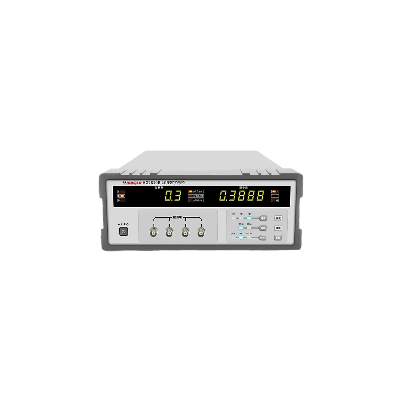
Bench LCR bridge in a grey case, with a five-digit LED display showing a primary and a secondary reading, four coaxial test terminals across the lower centre of the panel, a column of range and function keys at the right and the power switch at the left

HG2810B (6 models) · LCR Meters

Bench LCR Digital Bridge

Bench LCR bridges covering fixed-frequency and wide-band models, with 0.10% or 0.05% basic accuracy, five-terminal connections, bin sorting and optional RS232 and HANDLER interfaces for incoming inspection and production sorting.

Test frequencies
100 Hz, 120 Hz, 1 kHz and 10 kHz on the general models; up to 100 kHz on HG2817 and HG2817B; 8 points to 100 kHz on HG2817D; 37 points from 50 Hz to 200 kHz on HG2817A
Basic accuracy
0.10% on the general models; 0.05% on HG2816A and HG2817A
Test level
0.3 V on HG2810B; 0.1 V, 0.3 V or 1.0 V on most other models; 10 mV to 2.00 V in 10 mV steps on HG2816A and HG2817A
Display ranges
L 0.01 µH to 99999 H and C 0.01 pF to 99999 µF on the general models, with wider ranges on the LCD models
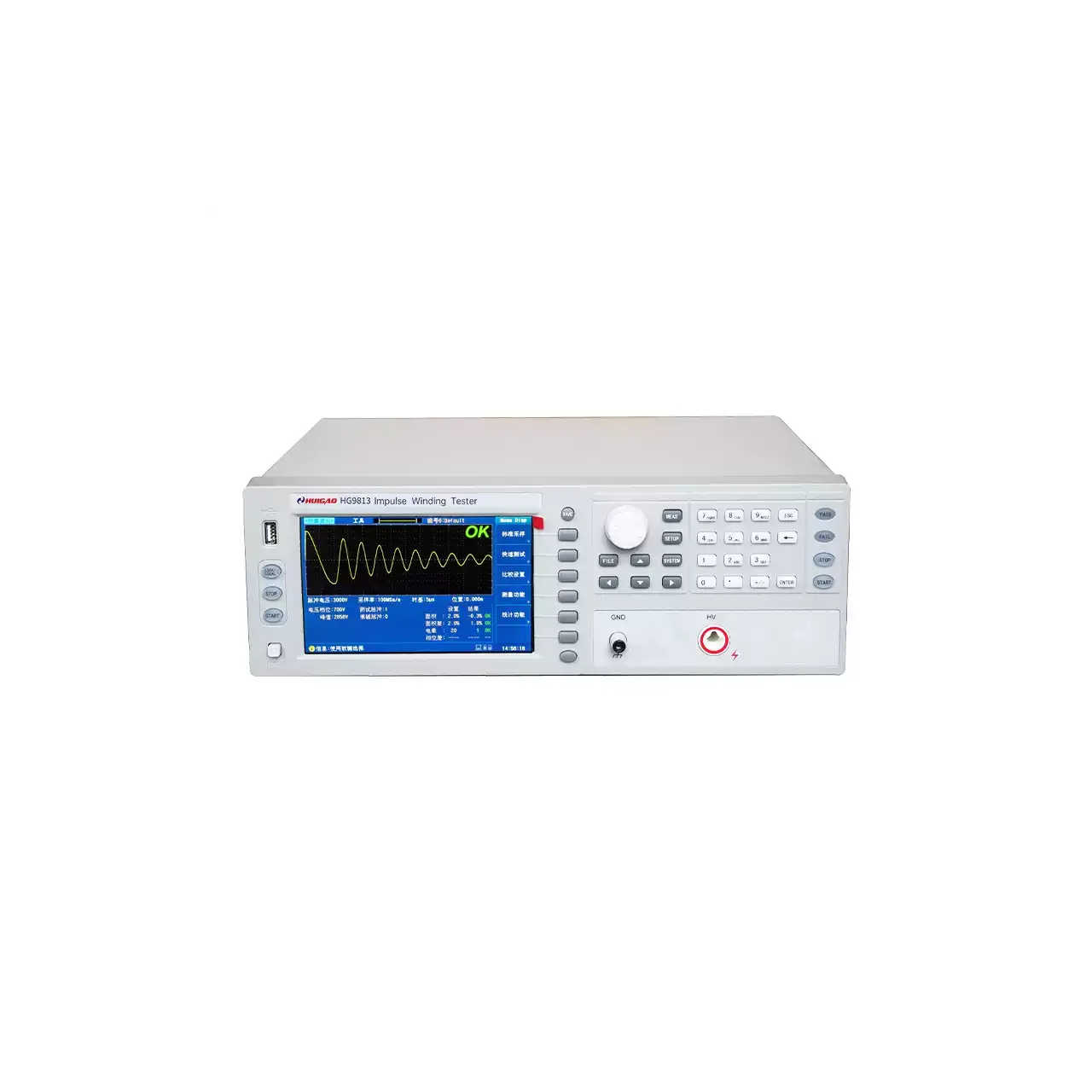
Bench winding insulation tester in a light grey case, with a 7-inch colour LCD at the left showing two overlaid pulse waveforms and a green OK result, a column of soft keys beside the screen, a rotary knob and numeric keypad at the right, and a ground terminal beside a red high-voltage terminal at the lower right

HG9813 (4 models) · LCR Meters

Winding Insulation Tester

Four impulse winding testers reaching up to 10 kV, with corona analysis, high-speed waveform capture, a 7-inch colour display and pass or fail outputs for inter-turn insulation testing of coils and windings.

Pulse voltage
100 V to 3000 V on HG9813, 100 V to 5000 V on HG9815, 200 V to 6000 V on HG9816 and 300 V to 10,000 V on HG9810, all in 10 V steps at 5% ±10 V
Pulse energy
0.09 J on HG9813, 0.25 J on HG9815, 0.36 J on HG9816 and 0.5 J on HG9810
Inductance range
≥10 µH on HG9813, HG9815 and HG9816; ≥50 µH on HG9810
Test speed
15 per second on HG9813 and HG9815, 12 on HG9816 and 8 on HG9810

Request a quotation for the HG7729

Send the configuration you need and we will confirm availability, lead time and terms. Minimum order quantity is 1 pc.

Request for quotation

Request a quotation - HG7729

Send the technical detail and we will confirm availability, lead time and terms. In-stock items ship within 48 hours; customized specifications typically take 2-10 days. Minimum order quantity is 1 pc.

The more of this you can give us, the fewer exchanges are needed before we can quote.
No file chosen
Datasheet, drawing, BOM or photograph. One file, up to 10 MB (PDF, Office, image or ZIP).

By submitting this form you agree that we may contact you about this enquiry. We do not sell or share enquiry data. See our privacy policy.

Items held in stock are dispatched within 48 hours of order confirmation. Customized specifications are produced to order and typically ship within 2 to 10 days. Transit time then depends on the shipping method and destination.

Request a Quote WhatsApp