Product type

LCR Meters

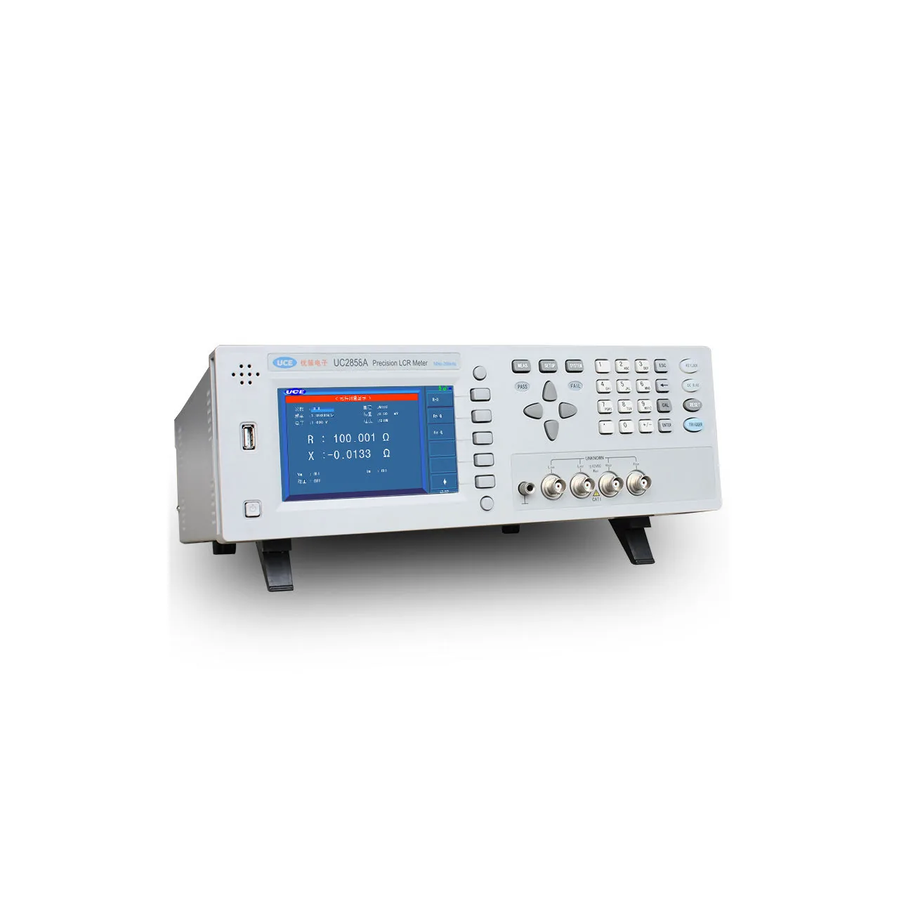
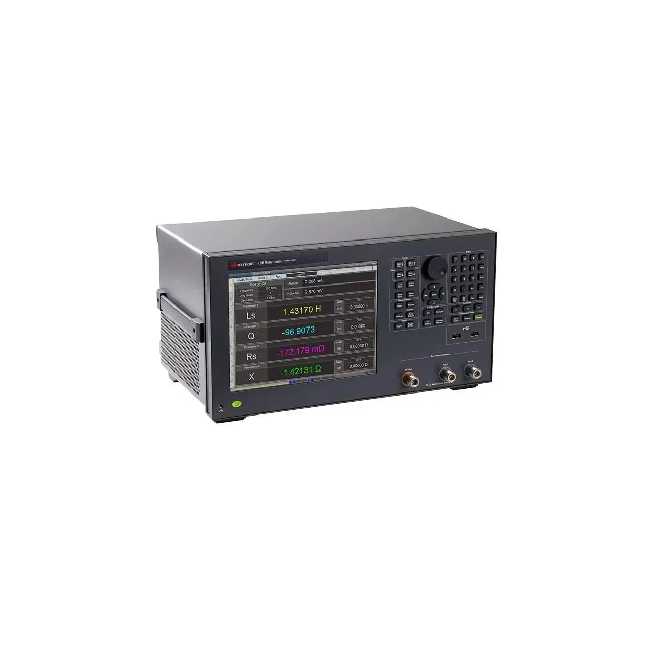
An LCR meter measures the inductance, capacitance or resistance of a component, and usually the loss associated with it, at a test condition the instrument sets. That condition is not a detail: the same capacitor has a different capacitance at a different frequency, a different signal level and a different direct bias, and an inductor’s value falls as the current through it rises. A figure quoted without its conditions is not comparable with a limit or with another instrument’s figure.

What an LCR meter is

An LCR meter measures the inductance, capacitance or resistance of a component, and usually the loss associated with it, at a test condition the instrument sets. That condition is not a detail: the same capacitor has a different capacitance at a different frequency, a different signal level and a different direct bias, and an inductor’s value falls as the current through it rises. A figure quoted without its conditions is not comparable with a limit or with another instrument’s figure.

The type covers more than the bench bridge. It includes impedance analysers that sweep a band rather than take a point, handheld meters for a quick check, and instruments that measure a component’s defect rather than its nominal value - capacitor leakage under bias, the number of turns on a coil, the balance of a three-phase winding. Those share the same bench and the same fixtures, and they are bought by the same people, which is why they sit together here.

Configuring one is therefore a matter of fixing the test conditions first and the instrument second. Frequency, signal level, direct bias, connection method and correction are what turn a display into a measurement, and the fixture is part of the measurement rather than an accessory. This page covers those decisions and the boundary against the general bench instrument and the safety tester.

How an LCR meter measures

The instrument applies an alternating signal to the component and measures the vector relationship between the voltage across it and the current through it. The magnitude gives the impedance and the phase separates the reactive part from the resistive part, which is how one measurement produces inductance or capacitance together with the loss term. The classical implementation is an auto-balancing bridge: the current through the device is converted to a voltage by an amplifier, and the two voltages are compared. At higher frequencies the bridge gives way to a reflection or transmission method, and the frequency band is what separates one class of instrument from another rather than the accuracy figure.

Whatever the method, the result includes the fixture. Leads add inductance, the fixture adds stray capacitance, and contact resistance appears in series with a low-value component. Open and short corrections measure those residuals at the test frequency and subtract them; a load correction adds a known reference. Without correction a low-impedance measurement is dominated by the leads and a high-impedance one by the stray capacitance, and both errors grow as the frequency rises. A four-terminal connection keeps the current-carrying leads separate from the sensing leads so that their impedance drops out.

Bias is the condition most often left out of a specification. A ceramic capacitor loses capacitance as the direct voltage across it rises, and a magnetic core saturates as the current through the winding rises, so a value measured at zero bias may not describe the component in its circuit. An internal bias source covers small components; a separate bias current source is needed where the current is larger, and its capability often limits the measurement rather than the meter. The signal level matters for the same reason: dielectric behaviour is not linear, so the alternating level at which the value was taken belongs with the number.

Configuration choices

Most of the specification is fixed by these decisions rather than by the accuracy class. Each one constrains the next, which is why they are settled in order.

ConfigurationOptions to fixWhat it actually decides
Frequency Fixed spot frequencies, a continuous tuning range, or a sweep across a bandWhether the value is a point check or a curve. Behaviour between the spot frequencies is invisible on a fixed-point instrument.
Test signal level A selectable alternating level, and whether it can be set independently of the rangeWhether the value describes the component at the level its circuit applies. Dielectric capacitance is level-dependent.
Direct bias An internal bias voltage, an external bias current source, or noneWhether the component is measured at its operating point. A capacitor or an inductor characterised at zero bias may be far from its in-circuit value.
Connection method Two-terminal, four-terminal or four-terminal pair, with the matching fixture or clipsHow much of the lead and contact impedance stays in the result, and therefore the smallest impedance that can be resolved.
Correction Open, short and load correction, and cable-length correction where an extension is usedWhether the fixture residuals are removed at the frequency of measurement. Without it the fixture is measured with the component.
Parameters displayed The primary value alone, or the value with the loss term, impedance and phaseWhether the figure the design calls for - a loss, a quality factor, an equivalent series resistance - can be read directly.
Comparison and sorting Limit comparison with a pass or fail indication, binning, or a plain displayWhether the instrument is used on a production bench to sort parts or in a laboratory to characterise one.
The measuring function Impedance at a test condition, or a defect test such as leakage, turns count or winding balanceWhether the question is what the component’s value is, or whether the component is sound. Both live in this type and the instruments are not interchangeable.

How to choose an LCR meter

FactorWhy it decides the answerHow to settle it before enquiring
What the component is, and the frequency it works at The frequency of interest fixes the instrument band, and often the measuring methodGive the component type and the frequency of the circuit, not only the nominal value.
The conditions the specification quotes Level and bias are part of the value, not an optional refinementState the alternating level and any direct bias the specification assumes.
The smallest impedance to be resolved It decides between a two-terminal and a four-terminal connectionGive the lowest value, and the size and termination of the part.
Whether one point or a curve is needed A sweep or an analyser answers a different question from a single-frequency bridgeSay whether the result is a value with a tolerance or a plot of behaviour.
Whether the part is sorted or characterised It fixes the comparator, the interface and the speedDescribe the bench: a laboratory measurement or a production decision.
Whether the real question is a defect Leakage, turns count and winding balance are measured by different instruments inside this typeState the failure being screened for, not only the parameter name.
The fixture and the part’s geometry A standard fixture cannot contact every package, and an improvised one adds errorGive the package, the lead spacing, and whether a custom fixture is expected.

If any of these are still open, send what is known. A quotation can be issued against a duty description and refined once the gaps are filled.

The nearest alternatives

These are the types an enquiry for an LCR meter usually turns out to be, and the point at which the choice is genuinely decided.

Nearest alternativeWhat separates it from an LCR meter
Electrical test equipment The bench bucket covers component testers that answer a different question - reverse leakage of a diode, sheet resistance of a film, the response of a piezoelectric plate. Those are not impedance measurements at a defined frequency, and an LCR meter with a component fixture is not a substitute for them.
Electrical safety testers Applies a high voltage to a finished product to prove its insulation. A capacitor leakage measurement applies a bias to a component and reads the current through the dielectric; the purpose is component quality, and the energy and the guarding are of a different order.
Power meters Measures the power a complete load draws in operation. An LCR meter measures one component at a defined condition, out of circuit; a power reading cannot be decomposed into the component values that produced it.

The boundary inside this type is the question being asked: a value at a test condition, a curve across a band, or a defect that makes the component unusable. The three need different instruments, and the first two need their conditions written down.

What to include in the enquiry

The first reply can be a quotation rather than a set of questions if the enquiry carries these. Where a figure is not known, send the duty description and we will confirm what it implies.

  1. The component type, its nominal value and its package
  2. The frequency band of interest, and whether a sweep is needed
  3. The alternating test level and the direct bias, with the current if bias is required
  4. The smallest impedance to be resolved, and the connection method it implies
  5. Whether the job is sorting, characterising or defect screening
  6. Quantity, destination port and required delivery date
Available products

15 models in LCR Meters

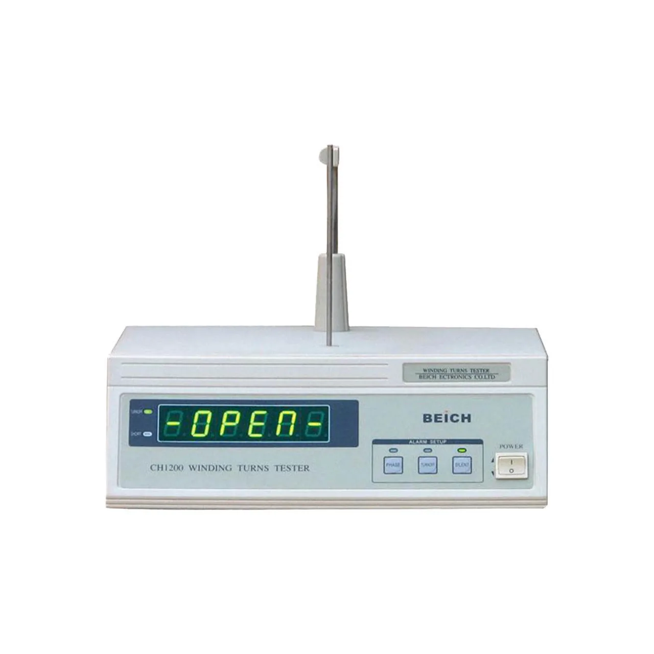
Bench turns tester with a vertical sensing rod rising from the top cover, a green LED display across the front showing an open-circuit indication, three alarm setup keys at the lower right and a power switch at the far right

CH1201 (4 models) · LCR Meters

Coil and Winding Turns Counter with DC Resistance

Bench turns counters for coils up to 80,000 turns, with automatic ranging, no calibration before a measurement, and DC resistance measurement on the two R models.

Turns range
1 to 80,000 on CH1201 and CH1201R; 1 to 30,000 on CH1200 and CH1200R
Turns accuracy
±0 turns to ±1 turn at the low end, then ±0.2% or ±0.3%, and ±0.5% at the top of the 80,000 range
Turns speed
3 readings per second on CH1201; 1.5 on CH1200
DC resistance
100 µΩ to 200 kΩ on CH1201R; 100 µΩ to 20 kΩ on CH1200R
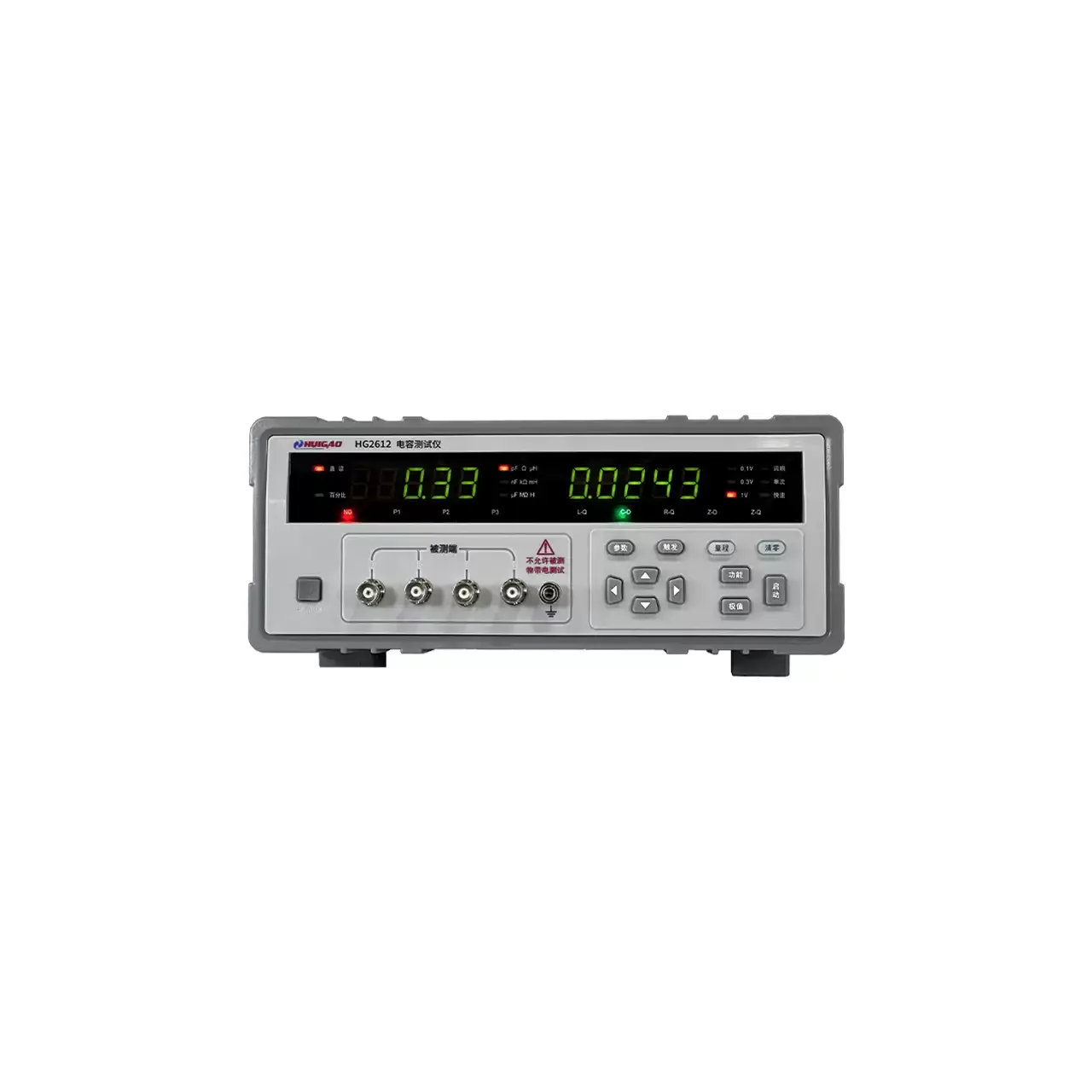
Bench capacitor test instrument seen from the front, with two green LED readouts across the upper panel, a row of four BNC terminals and a ground terminal along the lower left, and a keypad with arrow keys at the lower right

HG2611D · LCR Meters

Electrolytic Capacitor Leakage Current Tester

Bench leakage current tester for aluminium electrolytic capacitors, with a 0 to 500 V adjustable charging voltage, three current ranges from 0.01 µA to 30 mA and settable charge and discharge times.

Test voltage
0 to 500 V, continuously adjustable
Leakage ranges
0.01 to 3 µA, 3 µA to 3 mA, 3 mA to 30 mA
Reading error
±1% ±2 digits
Charge time
0 to 99 s, ±2%
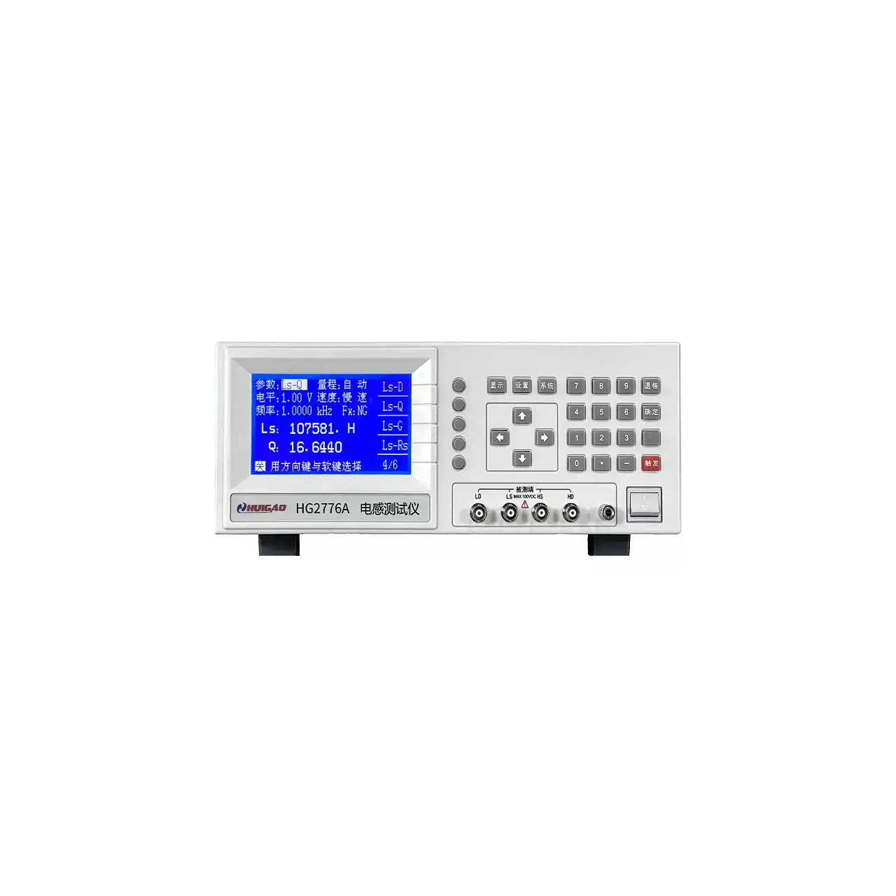
Benchtop inductance meter seen from the front, with a blue backlit LCD at the left showing an inductance value and a quality factor, a numeric keypad and arrow keys at the right, and four BNC terminals with a ground terminal along the lower front edge

HG2776A (2 models) · LCR Meters

Precision Inductance Meter with Wide Frequency Coverage

Two bench inductance meters, one covering 100 Hz to 200 kHz in 37 points at 0.05% accuracy and one covering four points to 10 kHz at 0.1%, both with four-terminal connection and multi-parameter display.

Test frequency
100 Hz to 200 kHz in 37 points on HG2776A; 100 Hz to 10 kHz in four points on HG2775A
Basic accuracy
0.05% on HG2776A; 0.1% on HG2775A
Test level
10 mV to 2.00 V in 10 mV steps on HG2776A; 0.1 V, 0.3 V or 1 V on HG2775A
Inductance range
0.01 nH to 9999.99 H
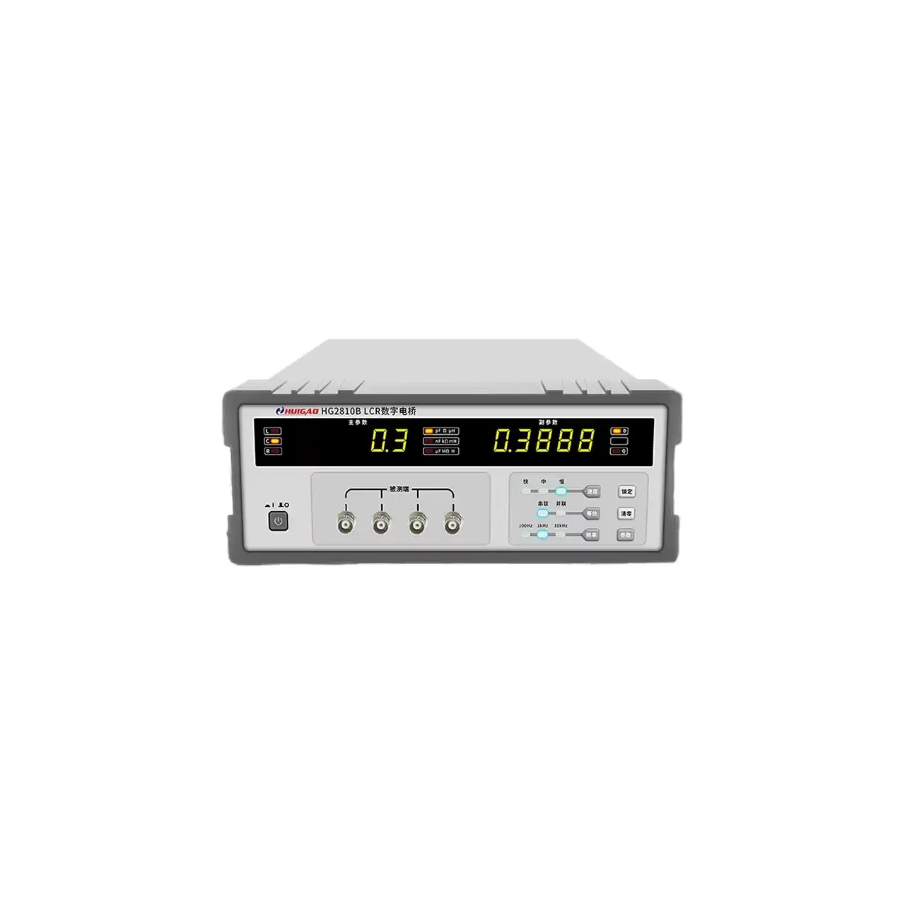
Bench LCR bridge in a grey case, with a five-digit LED display showing a primary and a secondary reading, four coaxial test terminals across the lower centre of the panel, a column of range and function keys at the right and the power switch at the left

HG2810B (6 models) · LCR Meters

Bench LCR Digital Bridge

Bench LCR bridges covering fixed-frequency and wide-band models, with 0.10% or 0.05% basic accuracy, five-terminal connections, bin sorting and optional RS232 and HANDLER interfaces for incoming inspection and production sorting.

Test frequencies
100 Hz, 120 Hz, 1 kHz and 10 kHz on the general models; up to 100 kHz on HG2817 and HG2817B; 8 points to 100 kHz on HG2817D; 37 points from 50 Hz to 200 kHz on HG2817A
Basic accuracy
0.10% on the general models; 0.05% on HG2816A and HG2817A
Test level
0.3 V on HG2810B; 0.1 V, 0.3 V or 1.0 V on most other models; 10 mV to 2.00 V in 10 mV steps on HG2816A and HG2817A
Display ranges
L 0.01 µH to 99999 H and C 0.01 pF to 99999 µF on the general models, with wider ranges on the LCD models
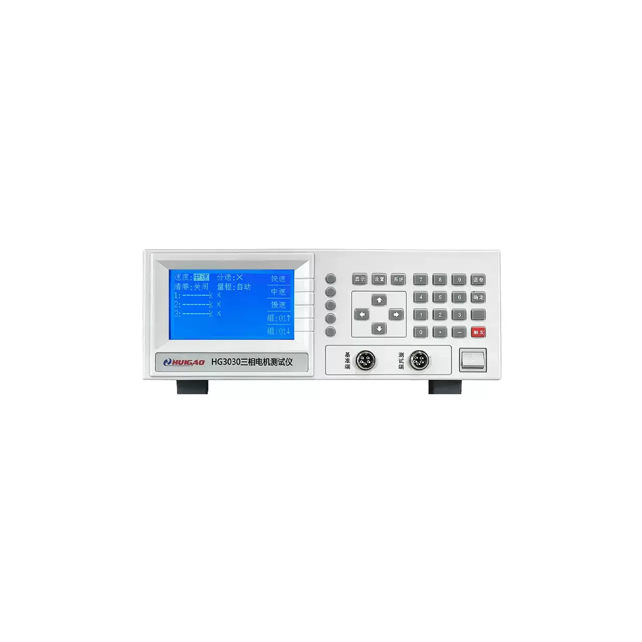
Benchtop winding resistance tester seen from the front, with a blue backlit LCD at the left showing three channel readouts stacked vertically, a numeric keypad and arrow keys at the right, and two circular multi-pin test connectors along the lower front edge beside the power switch

HG3030 · LCR Meters

Three-Phase Motor Winding Resistance Balance Tester

Three-channel DC resistance tester for motor windings, covering 10 µΩ to 2 MΩ at 0.05% accuracy, with simultaneous three-phase display, percentage comparison and pass or fail sorting.

Channels
Three, measured and displayed together
Resistance range
10 µΩ to 2 MΩ
Best accuracy
0.05%
Test current
DC 100 mA down to 1 µA, eight ranges
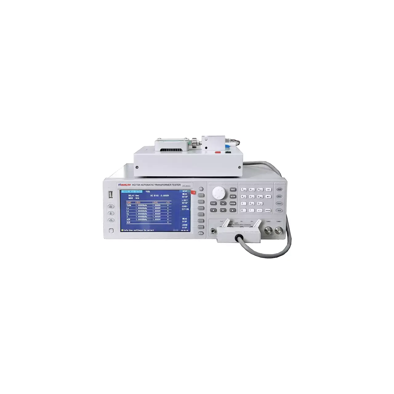
Bench transformer tester in a light grey case, with a colour LCD at the left listing turns ratio, inductance, leakage inductance and resistance readings, a column of soft keys and a numeric keypad at the right, and a test fixture resting on top of the case connected to the front panel by a ribbon cable and two coaxial leads

HG7729 (4 models) · LCR Meters

Transformer Comprehensive Tester

Four transformer testers with 20-channel scanning, LCR and DC resistance measurement at 0.05% basic accuracy, built-in DC bias and test frequencies from 20 Hz to 1 MHz for production testing of wound components.

Test frequency
20 Hz to 200 kHz on HG7729; 20 Hz to 300 kHz on HG7729A and HG7729B; 20 Hz to 1 MHz on HG7729C
Scanning
20-channel transformer scan on all four models
LCR parameters
|Z|, |Y|, C, L, X, B, R, G, D, Q and phase, plus DC resistance, turns and phase
Transformer scan parameters
Turns ratio, number of turns, phase, inductance, capacitance, leakage inductance, quality factor, AC resistance, DC resistance, balance, pin short and LED
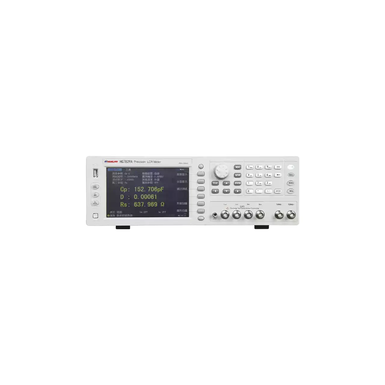
Precision LCR bridge seen from the front, with a colour TFT display at the left showing capacitance, dissipation factor and series resistance readings, a column of soft keys beside the display, a rotary knob and numeric keypad at the right, and a row of coaxial test terminals along the lower edge

HG7829A (3 models) · LCR Meters

Precision LCR Digital Bridge with Graphical Sweep

Precision bench LCR bridges covering 20 Hz to 300 kHz, 500 kHz or 1 MHz at 0.05% basic accuracy, with 1 mHz frequency resolution, a 7-inch colour display, 40-point list sweeps and graphical analysis.

Test frequency
20 Hz to 300 kHz on HG7829A, to 500 kHz on HG7829B, to 1 MHz on HG7829C
Frequency resolution
1 mHz, continuously variable
Basic accuracy
0.05%
Test level
5 mV to 2 V as standard; 5 mV to 10 V on the enhanced version
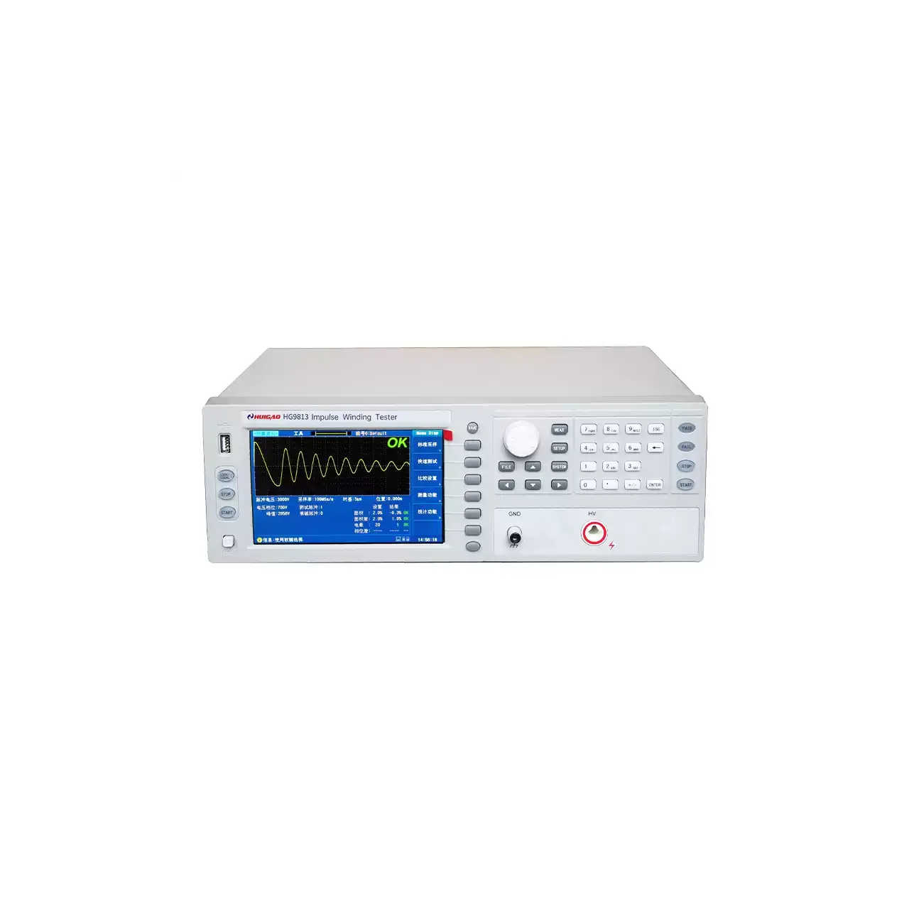
Bench winding insulation tester in a light grey case, with a 7-inch colour LCD at the left showing two overlaid pulse waveforms and a green OK result, a column of soft keys beside the screen, a rotary knob and numeric keypad at the right, and a ground terminal beside a red high-voltage terminal at the lower right

HG9813 (4 models) · LCR Meters

Winding Insulation Tester

Four impulse winding testers reaching up to 10 kV, with corona analysis, high-speed waveform capture, a 7-inch colour display and pass or fail outputs for inter-turn insulation testing of coils and windings.

Pulse voltage
100 V to 3000 V on HG9813, 100 V to 5000 V on HG9815, 200 V to 6000 V on HG9816 and 300 V to 10,000 V on HG9810, all in 10 V steps at 5% ±10 V
Pulse energy
0.09 J on HG9813, 0.25 J on HG9815, 0.36 J on HG9816 and 0.5 J on HG9810
Inductance range
≥10 µH on HG9813, HG9815 and HG9816; ≥50 µH on HG9810
Test speed
15 per second on HG9813 and HG9815, 12 on HG9816 and 8 on HG9810
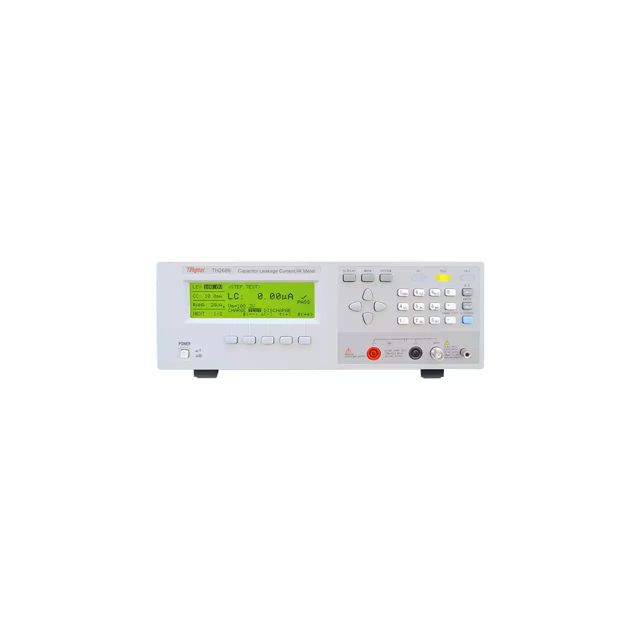
Bench capacitor leakage tester in a light grey case, with a backlit dot matrix display at the left showing a leakage current reading and charge status, function keys and a numeric keypad at the right, and a red high-voltage terminal beside two measurement terminals at the lower right

TH2689 (4 models) · LCR Meters

Capacitor Leakage Current Tester

Bench capacitor leakage testers with adjustable test voltage, leakage current measurement down to the nanoamp region, insulation resistance to 99.99 GΩ, timed charging and comparator limits.

Test voltage
1 V to 800 V on TH2689; 1 V to 500 V on TH2689A; 0 to 200 V and 0 to 500 V on TH2686N and TH2686C
Voltage accuracy
±(0.5% of setting + 0.2 V) on TH2689 and TH2689A; ±1% of setting + 1 digit on TH2686N
Leakage current range
0.001 µA to 20.00 mA on TH2689 and TH2689A; 10 nA to 19.99 mA with 1 nA resolution on TH2686N; 0 to 30 mA in 10 ranges on TH2686C
Insulation resistance
0.01 MΩ to 99.99 GΩ on TH2689 and TH2689A
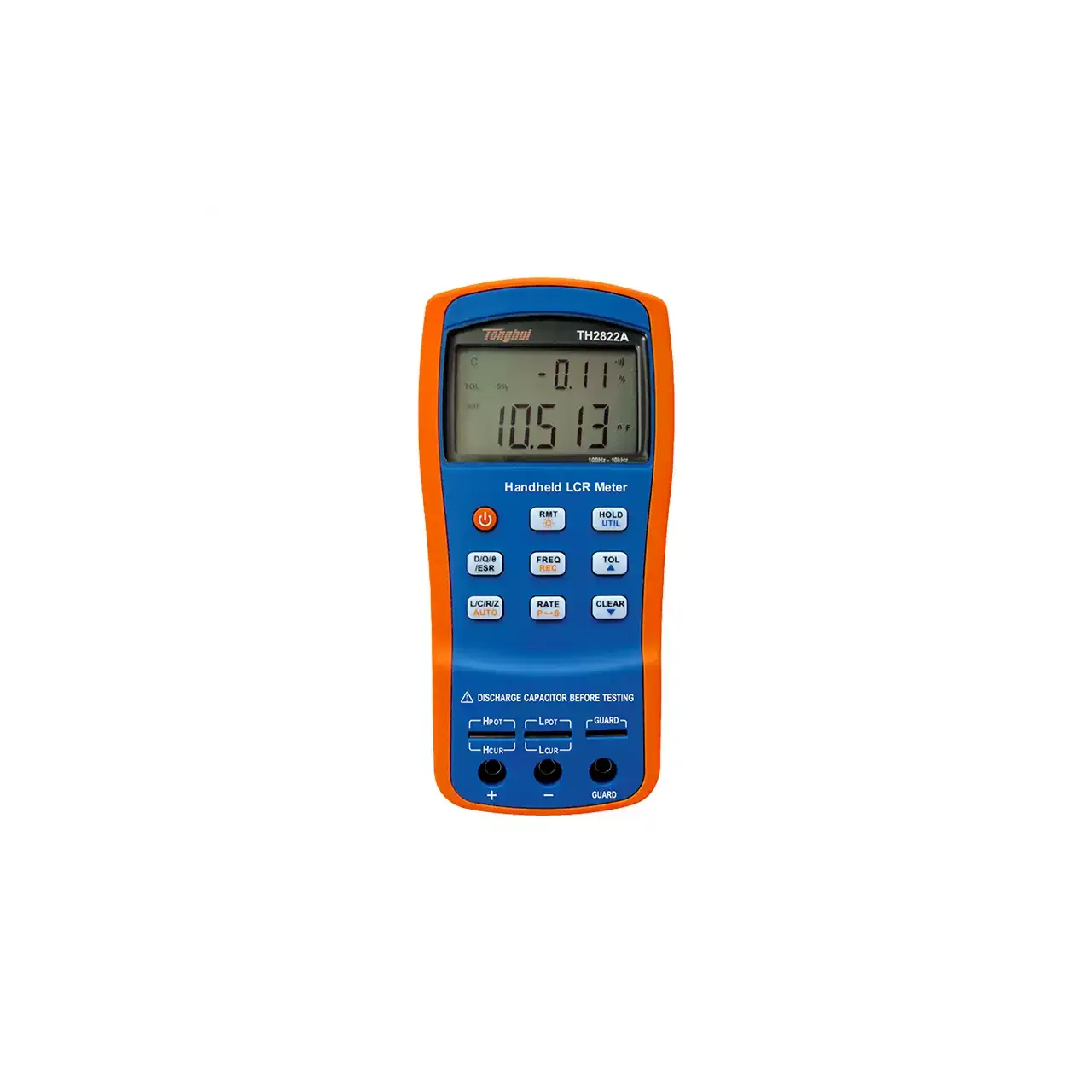
Hand-held LCR meter with an orange and blue case, shown from the front with the backlit display at the top showing a secondary and a primary reading, eight keys and a power button below it, and a five-terminal test slot above three banana sockets at the bottom

TH2822A (4 models) · LCR Meters

Handheld LCR Meter

Four handheld LCR meters covering 100 Hz to 100 kHz, with 0.25% or 0.1% basic accuracy, a dual parameter backlit display, automatic range and Mini-USB control, for measuring inductors, capacitors and resistors away from the bench.

Test frequencies
100 Hz, 120 Hz, 1 kHz and 10 kHz; 100 kHz added on TH2822C and TH2822E
Basic accuracy
0.25% on TH2822A and TH2822C; 0.1% on TH2822D and TH2822E
Measured parameters
L, C, R and Z as primary, with D, Q, phase angle and ESR as secondary; DC resistance on TH2822D and TH2822E
Display ranges
L 0.00 µH to 1000.0 H; C 0.00 pF to 20.000 mF; Z and R 0.0000 Ω to 10.000 MΩ
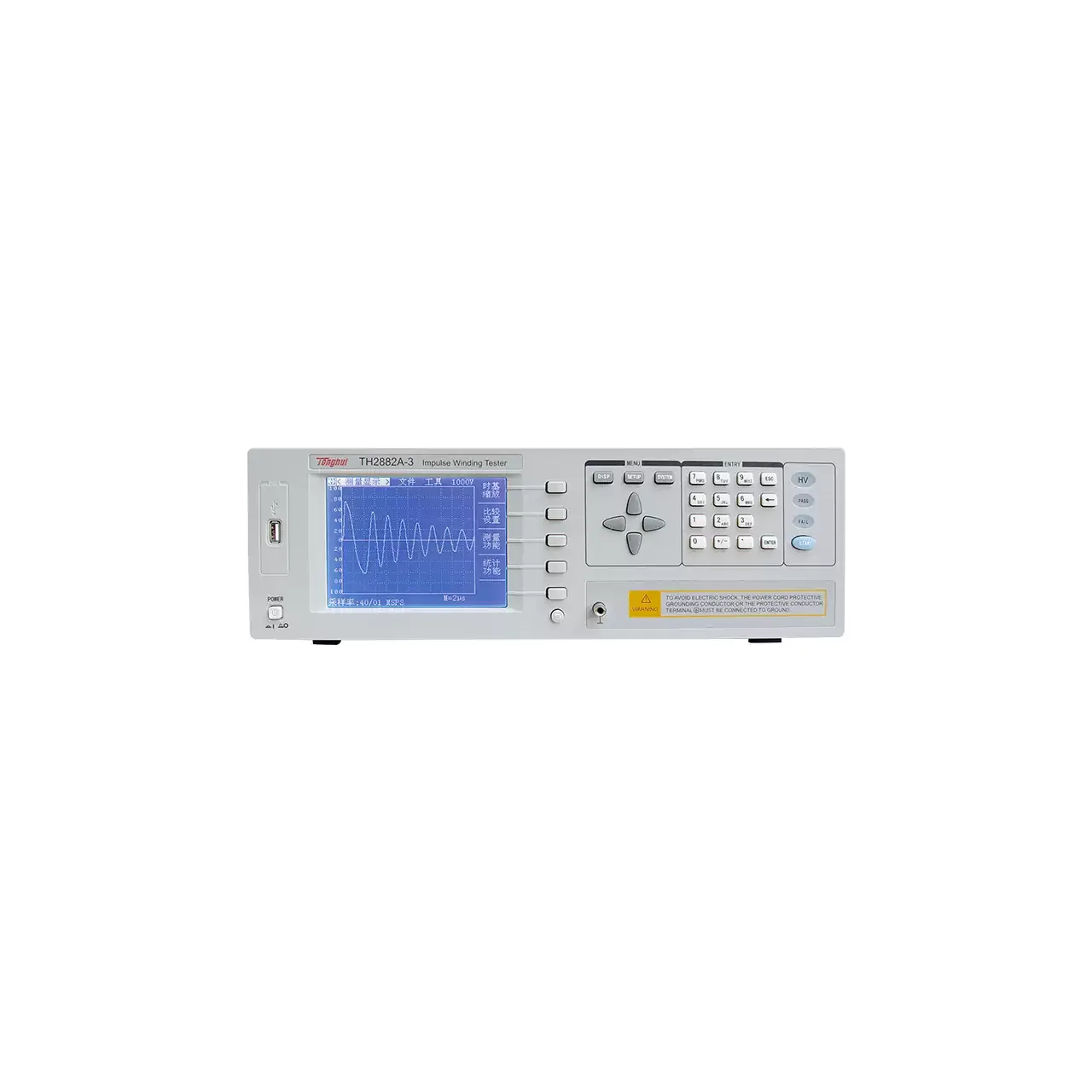
Bench impulse winding tester in a light grey case, with a colour LCD at the left showing a damped oscillatory waveform and two readings below it, a column of four soft keys beside the screen, a keypad and three status keys at the right, and a USB socket at the far left

TH2882A-3 (3 models) · LCR Meters

Impulse Winding Tester

Impulse winding testers that apply a high-voltage pulse to a coil and compare the response waveform against a reference, for finding inter-turn shorts, weak insulation and winding faults in single-phase and three-phase parts.

Output pulse voltage
300 V to 3000 V ±5% in 50 V steps on TH2882A-3; 500 V to 5000 V ±5% in 100 V steps on TH2882A-5; the model list gives the same 500 V to 5000 V for TH2882AS-5
Pulse energy
≤90 millijoules on TH2882A-3; ≤250 millijoules on TH2882A-5 and, in the model list, on TH2882AS-5
Inductance range
≥10 µH on TH2882A-3; ≥20 µH on TH2882A-5; ≥200 µH on TH2882AS-5
Waveform sampling
≤40 MSPS at 8 bit
Bench instrument seen from the front, with a colour display showing a decaying waveform trace across a graticule at the left, a column of soft keys beside it, a keypad and arrow pad at the right, and four high-voltage terminals with a ground terminal along the lower edge

ZX1373X-12A (3 models) · LCR Meters

High-Frequency LCR Bridge with DC Bias Current Source

Bias bridge instruments combining a high-frequency LCR meter with a 0 to 12 A or 0 to 25 A DC current source, with 0.25 mA current steps, sweeps up to 3600 s and stackable slaves to 225 A.

Bias current
0 to 12 A, 0 to 25 A, or up to 225 A with eight slaves stacked
Current resolution
0.25 mA on the lowest range
Maximum output voltage
11 V at every current setting
Bridge frequency
50 Hz to 200 kHz as standard; to 1 MHz or 2 MHz on the wide-band models
Bench instrument seen from the front, with a colour LCD showing a waveform trace across a graticule at the left, a column of soft keys beside it, a keypad and rotary controls at the right, and four high-voltage terminals with a ground terminal along the lower edge

ZX70A-200K (4 models) · LCR Meters

Impedance Analyzer for Piezoelectric and Ultrasonic Devices

Bench impedance analyzers covering 20 Hz to 5 MHz for piezoelectric ceramics, crystals and ultrasonic transducers, with four-wire Kelvin ports, frequency sweeps and a three-level comparator.

Frequency range
20 Hz to 200 kHz, 500 kHz, 1 MHz, 2 MHz or 5 MHz, by model
Basic accuracy
0.05% on the 200 kHz and 500 kHz models; 0.1% on the 1 MHz, 2 MHz and 5 MHz models
Frequency resolution
1 mHz
Impedance range
0.01 mΩ to 99.99 MΩ
Bench LCR meter seen from a low front-left angle, with a blue LCD at the left showing resistance and reactance readings, a column of soft keys beside it, an arrow pad and keypad at the right, and four BNC terminals along the lower edge

ZX8510BN (5 models) · LCR Meters

Compact LCR Digital Bridge with Fixed Frequency Points

Compact bench LCR bridges with four to ten test frequencies up to 100 kHz, basic accuracy from 0.2% to 0.05%, four-wire Kelvin terminals and three or four-bin sorting.

Test frequency
Four, six or ten fixed points between 50 Hz and 100 kHz, by model
Basic accuracy
0.2% on ZX8511DN; 0.1% on ZX8510BN, ZX8510BT and ZX8517BN; 0.05% or 0.1% on ZX8517BT depending on the table
Test level
0.1 V, 0.3 V or 1 V rms on the three-level models; 0.1 V to 2 V on the wide-level models
Impedance range
0.1 mΩ to 99.999 MΩ on the compact models; 0.01 mΩ to 99.9999 MΩ on the wide-level models
Bench instrument seen from the front left, with a colour display showing four measured parameters and their limits, a block of function keys and a numeric keypad at the right, and three coaxial connectors along the lower right edge

ZX8816 · LCR Meters

Low-Inductance Pulse Coil Tester

Pulse winding tester for coils from 0.1 µH to 1 mH, with four-terminal sensing, voltage compensation, breakdown voltage analysis, a 200 MHz sampler and a fastest test time of 18 ms.

Inductance range
0.1 µH to 1 mH
Peak test voltage
10 V to 1000 V
Voltage accuracy
±(1% of setting + 2.0 V)
Sampling
10 bits at 200 MHz, eight rate settings

Also in Electrical Test & Measurement

Other product types in this category

Every type we quote for under Electrical Test & Measurement. A type with no link yet is still quoted for - it is described on the Electrical Test & Measurement overview, and gets a page of its own as soon as a model is published against it.

Frequently asked

LCR Meters questions

Why does the same capacitor measure differently on two instruments?

Because the two are not measuring at the same condition. Frequency, alternating level and direct bias all change the value of a real component, and the fixture adds its own residuals unless it is corrected. Before treating the difference as an instrument fault, put the test conditions side by side: a meter set to a different frequency or a different level is answering a different question.

Do I need a four-terminal fixture?

It depends on the smallest impedance in the job. For a low-value capacitor, an equivalent series resistance or a small inductor, the lead and contact impedance is comparable with the part and a two-terminal connection cannot separate them; four terminals are required. For a large capacitance or a high-value inductor at a low frequency, the two-terminal fixture is adequate and simpler to use.

Is the capacitance range on a multimeter enough?

For a rough check of a large capacitor, it can be. It measures at one condition, with limited resolution and no loss term, so it cannot support a tolerance decision on a small part or a measurement of equivalent series resistance. If the figure has to be compared with a specification, a dedicated meter with a stated frequency and level is the instrument.

Quoting for LCR Meters

Send the specification and we will confirm the matching model, availability and lead time. Minimum order quantity is 1 pc.

Request for quotation

Request a quotation - LCR Meters

Send the technical detail and we will confirm availability, lead time and terms. In-stock items ship within 48 hours; customized specifications typically take 2-10 days. Minimum order quantity is 1 pc.

The more of this you can give us, the fewer exchanges are needed before we can quote.
No file chosen
Datasheet, drawing, BOM or photograph. One file, up to 10 MB (PDF, Office, image or ZIP).

By submitting this form you agree that we may contact you about this enquiry. We do not sell or share enquiry data. See our privacy policy.

Items held in stock are dispatched within 48 hours of order confirmation. Customized specifications are produced to order and typically ship within 2 to 10 days. Transit time then depends on the shipping method and destination.

Request a Quote WhatsApp