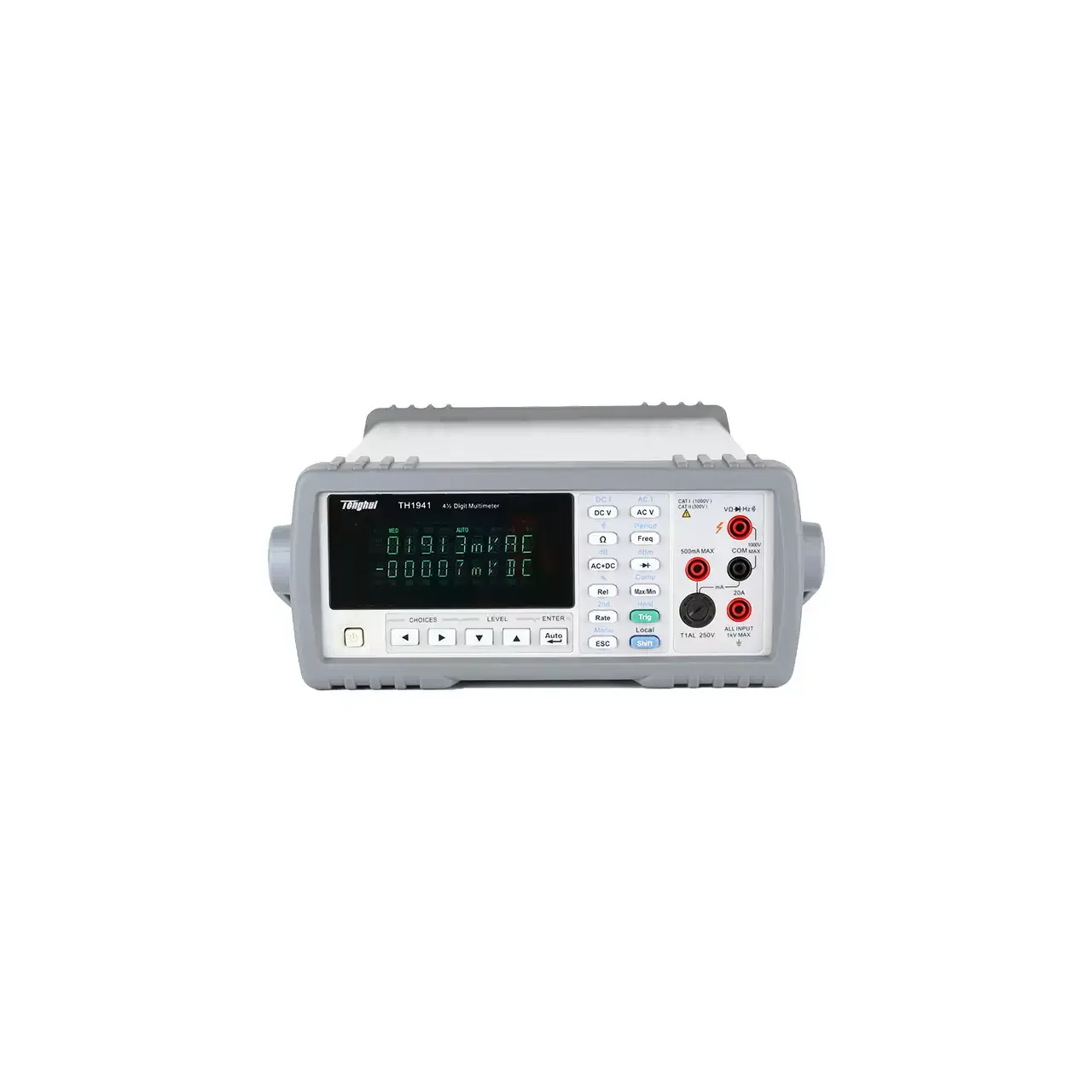
What a digital multimeter is
A digital multimeter measures the electrical quantities most often needed at a panel or a bench: voltage, current, resistance and continuity, with capacitance, frequency and temperature on many models. It is the instrument an electrician reaches for first, and the one most often bought on price alone, which is why the specifications that matter at the point of use are worth understanding before an order is placed.
Two figures do most of the work. The first is resolution, expressed as the digit count: a 3½-digit instrument is adequate for routine supply and control work, while 4½ digits and above are wanted where a small change has to be seen against a large value. The second is the accuracy statement, normally given as a percentage of the reading plus a number of digits, and it has to be read together with the range it applies to.
The third figure is the one most often overlooked. The safety category and voltage class describe what the instrument survives when it is connected to a live circuit with energy behind it, and they have nothing to do with how accurately it measures. An instrument used on industrial distribution needs a category rating appropriate to that point in the installation, and that is a safety decision rather than a performance one.
How a digital multimeter measures
The instrument converts the quantity under test into a small voltage and compares it against an internal reference. How that comparison is made - by a successive-approximation converter or by an integrating one - sets the trade-off between speed and noise rejection. An integrating instrument is slower but averages out mains-borne interference, which is why laboratory meters of that design hold a steady reading on a noisy supply.
Alternating quantities add a decision that is invisible on the display. A heater or a transformer fed by a clean sine wave gives the same answer whether the instrument averages the rectified waveform or computes the true root mean square; a variable-speed drive, a switching supply or a dimmer does not. On those loads an averaging instrument under-reports, sometimes substantially, and only a true-RMS instrument gives a figure comparable with the others taken on the same installation.
Current measurement is where a multimeter reaches its limit first. The instrument measures current by inserting a shunt into the circuit, so the whole load current passes through it, and the range tops out well below what an industrial feeder carries. Above that level, and always on a live feeder, the clamp meter is the appropriate instrument - which is the reason that family exists separately.
Configuration choices
Most of the specification is fixed by these decisions rather than by the accuracy class. Each one constrains the next, which is why they are settled in order.
| Configuration | Options to fix | What it actually decides |
| Resolution, or digit count | Commonly 3½, 4½ and higher counts | The smallest change that can be seen. It does not by itself say how accurate the reading is, and the two figures are often confused. |
| Basic accuracy on DC volts | Stated as a percentage of reading plus a number of counts, valid over a defined temperature band | Whether the reading can support the decision it is being used for. The figure has to be read against the range in use, not the instrument as a whole. |
| Measurement functions | Voltage, current, resistance and continuity as a minimum, with capacitance, frequency, diode test and temperature as additions | What still has to be carried in a second instrument. Fewer separate tools in one bag is a practical benefit rather than a specification one. |
| Alternating-signal response | Averaging, or true root mean square | Whether readings taken on drives, switching supplies and other non-sinusoidal loads are comparable with readings taken on clean mains. |
| Safety category and voltage class | Category ratings stepping up from low-energy electronics to the supply entry point | What the instrument is rated to survive in the event of a transient while connected. This is a safety limit, not an accuracy figure. |
| Input impedance | A high fixed impedance on most ranges, with a low-impedance mode on some models | Whether a stray induced voltage is read as if it were real. A low-impedance mode gives a truthful zero on a conductor that is not actually energised. |
| Current range and fuse arrangement | The internal shunt rating, and the fuse type and how easily it is reached | How much current may be passed at all, and whether a mistake costs a replacement fuse or a repair. |
| Data handling and accessories | Logging, an optical or wired interface, and the probes and clips supplied | Whether readings can be recorded rather than written down, and whether the probes suit the terminals being measured. |
How to choose a digital multimeter
| Factor | Why it decides the answer | How to settle it before enquiring |
|---|
| What is actually measured | The function list is driven by the job, not by the price band | List the quantities and the ranges at which they occur on the actual installation. |
| Accuracy needed at the low end | A small quantity read on an over-large range inherits the range error | State the smallest value that has to be resolved, not only the largest. |
| The energy behind the point of measurement | It fixes the required category rating, and it sets a floor on the instrument whatever the accuracy | Identify where in the distribution the measurement is taken, from electronics up to the service entry. |
| Waveform of the supply | Non-sinusoidal loads make an averaging instrument misleading | Confirm whether drives, inverters or electronic loads are present on the circuit. |
| Current level | Above a few amperes the clamp becomes the safer instrument | Give the current to be measured and the size of the conductor. |
| Whether readings must be kept | Recording and interface options are only worth paying for if the data is used | Say whether results are logged, trended, or only observed at the time. |
| Calibration requirement | A traceable certificate or a defined interval may be imposed by the customer’s own quality system | State whether a certificate is required with the instrument, and the interval at which it will be returned for calibration. |
If any of these are still open, send what is known. A quotation can be issued against a duty description and refined once the gaps are filled.
The nearest alternatives
These are the types an enquiry for a digital multimeter usually turns out to be, and the point at which the choice is genuinely decided.
| Nearest alternative | What separates it from a multimeter |
| Clamp meters | Measure current by surrounding the conductor rather than interrupting it, so a feeder can be read without opening the circuit. Lower accuracy and a narrower function set are the trade for that; where the current is small, or the circuit must not be broken at all, the multimeter remains the answer. |
| Voltage testers | A safety instrument rather than a measuring one, built to prove the absence of voltage before work begins. Its indications are coarse by design, and it is not a substitute for a reading - but the two duties are different and both are usually required. |
| Insulation resistance testers | Applies a high direct voltage to find leakage through insulation, which is a test rather than a measurement of a live circuit. A multimeter cannot perform it, and the insulation tester cannot report the operating quantities a multimeter measures. |
| LCR meters | Measures inductance and capacitance as primary quantities at defined test frequencies, which is what component work needs. A multimeter that offers capacitance usually does so as a convenience on small values and at one test condition. |
| Power meters | Reports real power, power factor and energy rather than the individual electrical quantities. Where the purpose is consumption or efficiency, arithmetic performed on separate voltage and current readings does not replace the measurement. |
| Circuit testers | Intended to confirm wiring and continuity on an installation rather than to quantify. It is quicker and safer for a socket or a spur check, and it does not report a value that can be recorded against a tolerance. |
The boundary worth settling first is current. Where the conductor carries more than a few amperes, or cannot be broken to insert an instrument, the clamp meter takes over and the multimeter is the wrong tool regardless of its specification.
What to include in the enquiry
The first reply can be a quotation rather than a set of questions if the enquiry carries these. Where a figure is not known, send the duty description and we will confirm what it implies.
- The quantities to be measured, with the range each occurs at
- The smallest value that has to be resolved
- Where in the installation the measurement is taken, to fix the safety category
- Whether drives, inverters or electronic loads are present on the circuit
- Current to be measured, and the conductor size
- Whether readings must be logged or exported
- Whether a calibration certificate is required, and at what interval
- Probe and accessory needs for the terminals in use
- Quantity, destination port and required delivery date