What a digital power meter is
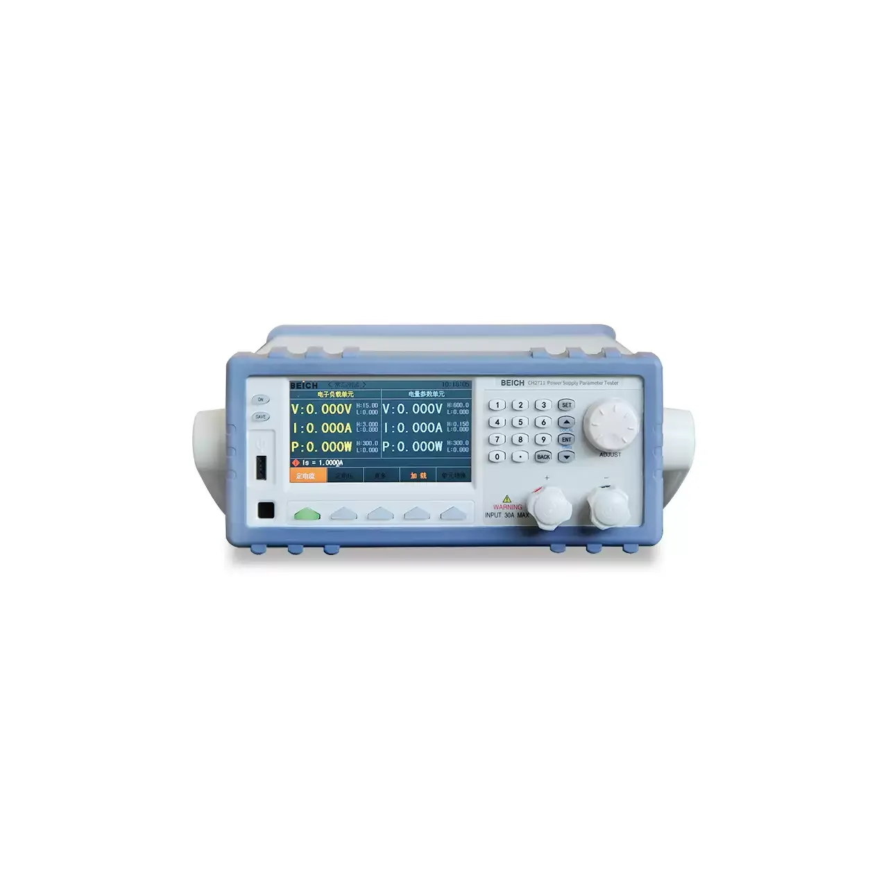
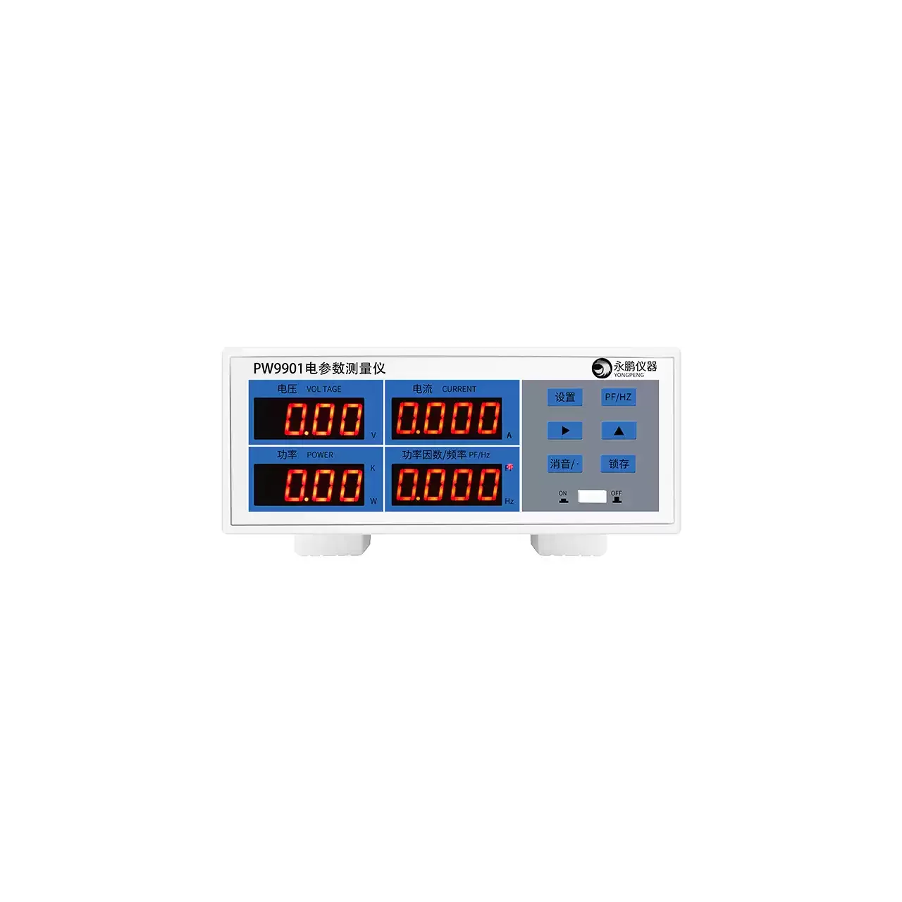
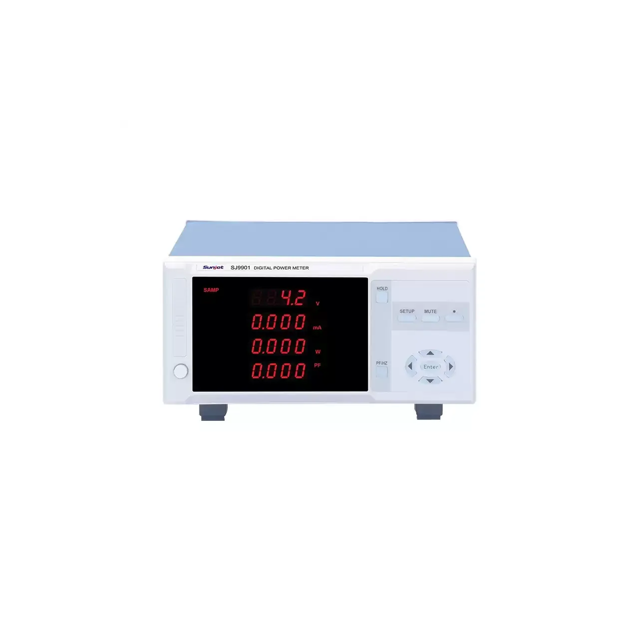
A digital power meter measures the electrical quantities a load actually presents rather than the ones a supply is supposed to provide. Voltage and current are read simultaneously, and active power, power factor, apparent power, reactive power and frequency are computed from that pair. On most panel instruments an energy total is accumulated as well, so a run can be reported as consumption rather than as an instantaneous reading.
That simultaneous pair is what separates the type from the instruments around it. A multimeter reads voltage or current one at a time and settles by hand; a clamp meter reads current without breaking the circuit but does not compute power; an energy meter is built to accumulate a quantity over a billing period rather than to show an engineer what a load is doing this second. A power meter sits at the bench or at the end of a test line, where the question is what the unit under test draws and how efficiently it draws it.
The choice within the type turns on two answers rather than on the accuracy class. Whether the measurement is AC only or has to cover DC decides the series outright, because an AC-only instrument cannot characterise the DC output of an adapter or a supply. How wide the current span has to be, at both ends, decides the range: the top end fixes the largest load that can be tested, and the bottom end decides whether a standby figure is a measurement or merely a number on a display.
How a digital power meter measures
The instrument samples the voltage across the load and the current through it, converts both to digital form against the same timebase, and multiplies them point by point. Averaging that product over a whole number of cycles gives active power, and dividing it by the product of the root-mean-square voltage and current gives power factor. Because the computation is done on samples rather than on rectified averages, the result stays correct when the waveform is not a clean sine wave, which covers every switched-mode supply, dimmer and variable-speed drive.
Where the waveform is distorted, the difference between a true-RMS instrument and an averaging one becomes visible on the display rather than in the manual. An averaging instrument is calibrated to read correctly on a sine wave and under-reports as the waveform departs from it; a true-RMS instrument computes the heating equivalent of the waveform and therefore agrees with the other readings taken on the same installation. The gap is small on a resistive heater and can be substantial on a load with a poor crest factor.
Current is where the range narrows first. At the low end the resolution of the current channel sets the smallest figure that means anything, which is why efficiency work on standby consumption needs an instrument whose bottom range sits in the tens or hundreds of microamperes rather than in milliamperes. At the top end the current passes through the instrument on the lower ranges and through an external shunt on the highest ones, so a specification that reaches two hundred amperes is really a statement about which shunt is used with it.
Configuration choices
Most of the specification is fixed by these decisions rather than by the accuracy class. Each one constrains the next, which is why they are settled in order.
| Configuration | Options to fix | What it actually decides |
| Measurement mode | AC only, or AC and DC | Whether the DC output of an adapter, a charger or a supply can be characterised at all. An AC-only instrument is not a cheaper substitute for that duty. |
| Current range, lower end | A few milliamperes, or down to tens of microamperes | Whether standby and no-load power are measurable or only displayed. Efficiency work sits below a few milliamperes of load current. |
| Current range, upper end | From twenty amperes upwards, with an external shunt beyond a certain point | The largest load that can be tested, and whether a shunt is part of the configuration rather than an accessory ordered with it. |
| Voltage input and range switching | A fixed range, or automatic switching across the working span | How much of the operator’s attention the instrument needs. Automatic ranging removes a whole class of mis-set-range errors from a production test. |
| Accuracy class and its reference | A percentage of reading, of full scale or of span, quoted against a named standard | Whether two instruments will agree. A figure without its reference cannot be compared with another instrument’s figure. |
| Computation set | Voltage, current, active power and frequency, or the full set including apparent power, reactive power, phase angle and energy | Whether the efficiency question can be answered from one instrument or a second calculation has to be done alongside it. |
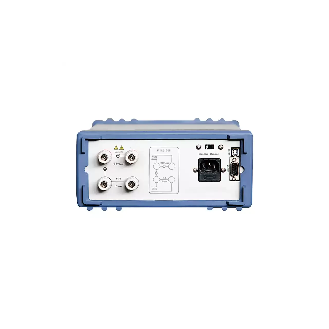
| Interface | A serial port as standard, with an isolated bus or a relay output as an option | Whether results are transcribed by hand or read by a test system. Where a line is automated, an instrument without a bus is a manual step in it. |
| Mounting | A bench case, or a panel instrument with a cut-out | Whether the meter stands beside the unit under test or becomes part of the test bench. The cut-out is fixed by the body and has to be provided for on the panel. |
The interface and the mounting are decided early, because both are fixed when the unit is built and neither can be added afterwards.
How to choose a digital power meter
| Decision | What settles it | What to ask |
|---|
| What the reading is for | Verification of a rating, or measurement of an efficiency figure | Whether the worst case is at full load, where the top of the range matters, or at no load, where the bottom of the range does. |
| Whether DC has to be covered | The output of the unit under test | An adapter, a charger or a DC supply forces an AC-and-DC instrument; a mains-fed motor does not. |
| The smallest current that must mean something | The consumption figure the test standard requires | Standby and no-load limits are quoted in fractions of a watt, which fixes the current floor before the accuracy class is discussed. |
| The largest current to be tested | The rating of the unit under test, with margin | Whether the highest range is reached through the instrument or through an external shunt, and whether the shunt is supplied. |
| The waveform at the load | Whether the load is resistive or electronic | A switched-mode supply, a dimmer or a drive requires true-RMS conversion, and the difference is invisible on a resistive load. |
| Whether a test system reads the result | The presence of a controller or a data-logging step | An isolated bus or a relay output is ordered with the instrument and cannot be fitted later. |
| Whether consumption over a run is reported | A duty cycle rather than a single operating point | Energy accumulation and elapsed time have to be in the computation set, and the interval has to be defined. |
If any of these are still open, send what is known. A quotation can be issued against a duty description and refined once the gaps are filled.
The nearest alternatives
These are the types an enquiry for a digital power meter usually turns out to be, and the point at which the choice is genuinely decided.
| Nearest alternative | What separates it from a digital power meter |
| Digital multimeters | Read voltage or current one quantity at a time and settle by hand, so they cannot produce a power figure. They are the right tool for confirming a supply is present and the wrong one for measuring what a load draws. |
| Clamp meters | Read current without breaking the circuit by enclosing the conductor, which makes them the instrument for a feeder that cannot be interrupted. They give a current figure and not a power figure. |
| Energy meters | Accumulate a quantity over a billing period rather than displaying the operating point of a load. An energy meter answers how much was used; a power meter answers how it was being used. |
| Power quality analyzers | Record harmonics, distortion, transients and unbalance over time. A power meter states the fundamental figures and does not diagnose the waveform that produced them. |
| Current meters | Measure the current in a loop or a conductor on its own, often as a panel indicator. They carry one quantity to a control room rather than characterising a load at a test bench. |
The boundary worth settling first is mode. If any part of the duty is DC, that decides the series, and an AC-only instrument should not be quoted for it.
What to include in the enquiry
The first reply can be a quotation rather than a set of questions if the enquiry carries these. Where a figure is not known, send the duty description and we will confirm what it implies.
- The supply the unit under test runs from, and whether the measurement is AC only or AC and DC
- The largest load current to be tested, and the smallest current that still has to be measurable
- The accuracy figure the test standard requires, and the standard it is quoted against
- Whether standby or no-load consumption is part of the test, and the limit that applies
- The waveform at the load, for example a resistive heater or a switched-mode supply
- Whether a controller or a test system will read the instrument, and over which interface
- Whether energy accumulation over a run has to be reported
- Mounting: on a bench, or set into a panel, with the panel cut-out dimension