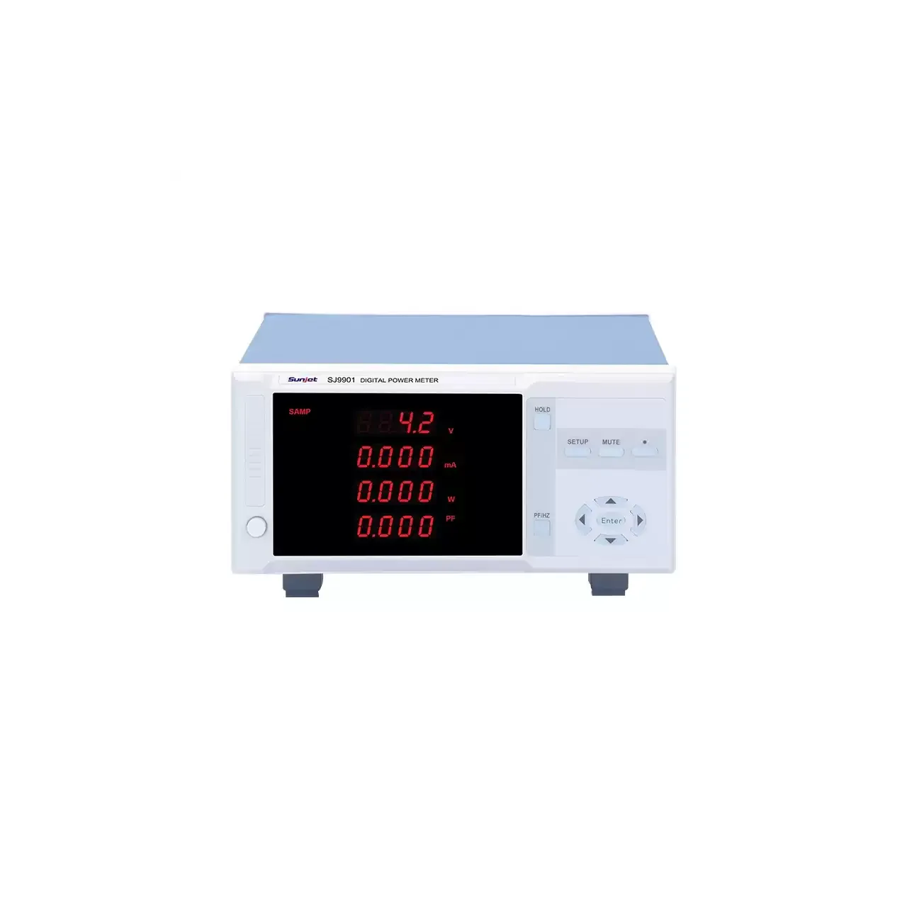
- Measurement
- Voltage, current, active power, power factor and frequency; the base model has no frequency display
- Voltage range
- 5 to 400 V AC; 2 to 400 V on two models as carded; 800 V peak
- Current range
- 5 mA to 20 A on the base rating, and up to 200 A on the highest rating of the alarm model
- Power range
- 0.1 W to 16.5 kW
- Accuracy
- ±(0.4% of reading + 0.1% of range + 1 digit); the cards quote 0.5% instead
- Reading rate
- 5 readings per second
- Display
- Four-window LED, one quantity per window
- Input impedance
- About 2 MΩ on every voltage range
- Outputs
- RS232, RS485 or relay, listed as optional; Modbus or a custom protocol
- Body
- 285 × 210 × 105 mm, about 2.3 kg, with a 210 × 90 mm panel cut-out
A power meter range is usually sold on its widest current rating, but that rating is the least interesting thing about it. What decides whether a bench can use it is the bottom of the scale, the frequency band it accepts, and whether the output can be wired into a test station.
Product overview
Five single-phase models share one measuring engine and one four-window display. They separate along four lines: current rating, the lowest current that can be resolved, the frequency band, and whether a direct-current input is fitted.
The base model indicates only. The alarm model carries the widest spread of current ratings and is the one that can be ordered with a serial port, a relay output or an energy function. Two efficiency models drop the bottom of the scale far below a milliamp. One model accepts direct current, and one is carded as a harmonic instrument.
The instrument is built as a case that can stand on a bench or drop into a panel cut-out, and the same body is used across the range.
How the meter works
Voltage and current are sampled together and multiplied to give instantaneous power, which is then averaged over a whole number of cycles. Power factor is computed from the result rather than measured separately, so it carries the error of both input channels, and the figure becomes unreliable as the load approaches no load.
The voltage channel changes range automatically; the current channel does not, because the shunt is fixed by the rating ordered. That asymmetry is the reason the current rating has to be chosen against both ends of the test rather than against the largest load alone.
The fourth window carries either power factor or frequency, selected from the front panel. The base model has no frequency display at all, which is worth knowing before a test procedure assumes one.
How to select the right model
Start with the current, at both ends. A bench that tests appliances up to a few tens of amps is served by the middle ratings; a bench that tests large units needs the top rating and accepts a poorer bottom of scale as the price. Where both a large load and a standby figure have to be measured, two instruments are usually cheaper than one compromise.
Then the frequency. The efficiency models cover a band wide enough for a variable-frequency supply; the harmonic model is carded for the mains band only. A test on an inverter output cannot be moved to the narrower model by changing a setting.
Then the mode. Only one model takes a direct-current input, and no other model can be substituted for an adapter or a DC supply.
Finally the output. The serial, relay and energy versions are separate order lines at the same rating, so the output has to be decided with the rating rather than after it.
Measurement limitations and selection considerations
The accuracy is quoted in the form that matters, as a reading term plus a range term plus a digit. That form behaves differently from a single percentage: at the bottom of a range the range term dominates, so a reading taken just above the floor of the scale is the least accurate one the instrument produces. A class figure quoted alone would hide this.
Power factor is computed, not measured, and it degrades as the current falls. On a lightly loaded motor or a supply at no load, the power factor reading is arithmetically correct and practically meaningless, because the denominator is the product of two small numbers each carrying its own error.
The range measures a single-phase circuit. A three-phase load needs either three instruments or a three-phase model, and the material describes one such model only in its model cards, without a parameter table behind it.
Nothing in the material describes the rear terminals, the operating environment or the contents of the carton, and the accuracy is not tied to a published standard. Those are questions for the supplier rather than assumptions for the bench.
Every value below is taken from source documentation. Where a parameter is not stated in the available material it is marked as information required rather than estimated.