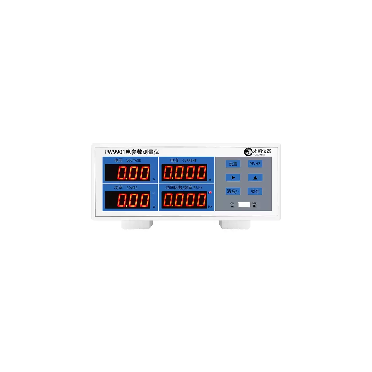
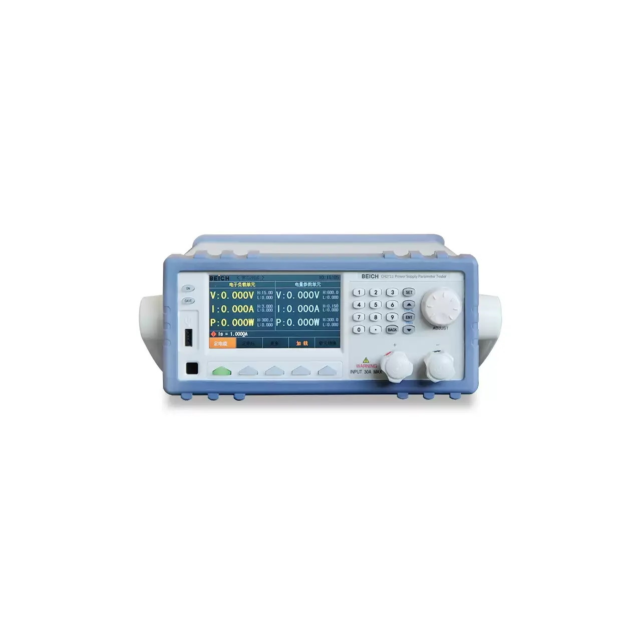
- Channels
- One, single-phase
- Voltage
- 5 to 600 V AC, 700 V AC peak, 0.1 V resolution
- Current
- 10 mA to 10 A or 20 A as printed; 5 mA to 20 A, 0.05 mA to 5 A or 0.5 mA to 40 A by model
- Power
- 0.1 W to 12 kW; 0.001 W to 3000 W on the low-current model
- Accuracy
- ±0.4% of reading + 0.1% of range; a 0.5 class figure is also stated
- Harmonics
- Orders 1 to 50, on CH2811 only
- Measurement method
- True root mean square, automatic ranging
- Display
- 4.3 inch colour thin-film transistor screen with waveform and harmonic views
- Interfaces
- RS-232C and USB device as standard, USB host for data storage, wireless router optional
- Body
- 215 × 88 × 312 mm, about 3 kg, in a standard rack width
One channel is enough for most bench work, provided the channel spans the right two decades. This range is built around that idea: one measuring platform, five spans, and one model that adds harmonic analysis.
Product overview
The five models share a screen, a keypad and a measuring engine. What changes is the current channel: a general span, a direct-current version of the same span, a harmonic version, a span that reaches two decades lower, and one that reaches twice as high.
Every model measures voltage, current, active power, power factor, frequency and energy, and every model displays waveforms. The differences that decide a purchase are the two ends of the current span, whether a direct input is fitted, and whether harmonic orders are reported.
The case is a standard rack width with rubber frames at the front and rear, so the same instrument can stand on a bench or be built into a console.
How the meter works
Voltage and current are sampled, converted to true root mean square values and multiplied to give active power. Because both channels are converted before multiplication, the result holds for a distorted waveform as well as a clean one; an instrument that averages the rectified waveform would under-read on exactly the loads this meter is bought to test.
Power factor is computed from the two measured quantities rather than measured separately. That makes it exact arithmetic and poor metrology at the same time: as the current falls towards zero, both terms in the denominator become small and their errors dominate the ratio.
On the harmonic model the sampled waveform is resolved into orders, and the display can show the spectrum instead of a number. The material gives the order count but not the method, the accuracy or the quantities analysed.
How to select the right model
Start at both ends of the current. The highest figure the test will reach decides between the general, the harmonic and the high-current models; the lowest figure that has to be resolved decides whether the general model is adequate at all or whether the low-current model is required. These two ends are independent, and a bench that needs both a large load and a standby figure may need two instruments.
Then the input mode. Only one model accepts a direct voltage and current, and no setting on the others substitutes for it.
Then the harmonic function, which is confined to one model and cannot be added to another. Where a test calls for distortion, the choice is made there; where it does not, the other four are simpler.
Energy is measured across the range, but the accuracy of that function is not stated, so it should not be specified for a billing or compliance purpose without confirmation.
Measurement limitations and selection considerations
The frequency band is narrow. A meter specified over the mains band will not give a meaningful reading on the output of a variable-frequency drive or an inverter, and the range contains no model that covers a wider band. That is a limitation of the platform rather than of one model.
The voltage channel starts at 5 V, so a very low-voltage output is below the floor and cannot be measured on any model. The power range starts at a tenth of a watt on four models, which is well above the standby consumption of a small charger.
Harmonic orders to the fiftieth are a count, not an accuracy. Without a stated amplitude error, a phase reference and a method, the function cannot be used to demonstrate compliance with a distortion limit; it is a diagnostic view until those figures are supplied.
The instrument measures one single-phase channel. A three-phase load needs three instruments or a three-phase model, and nothing in this range is three-phase.
Every value below is taken from source documentation. Where a parameter is not stated in the available material it is marked as information required rather than estimated.