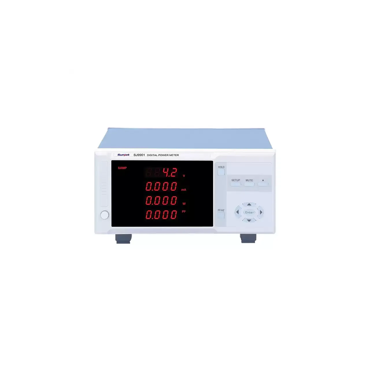
- Load ratings
- 0 to 150 V at 0.1 mA to 30 A, or 0 to 500 V at 0.1 mA to 15 A, 150 W
- Load modes
- Constant current, constant voltage, constant resistance and constant power
- Load resolution
- 0.1 mV and 0.1 mA at the bottom of the scale
- Meter input
- 5 to 600 V AC, 10 mA to 20 A AC; 0.05 mA to 5 A AC on the two small-current models
- Meter power range
- 0.1 W to 12 kW; 0.001 W to 3000 W on the two small-current models
- Meter accuracy
- ±0.4% of reading + 0.1% of range
- Meter method
- True root mean square, single-phase
- Display
- 4.3 inch colour thin-film transistor screen, both units shown together
- Interfaces
- RS-232C, USB device, USB host for data storage and a HANDLER output
- Body
- 215 × 88 × 335 mm, 6 kg in the parameter table and about 6.5 kg on the dimension page
A supply is usually judged twice: once for what it delivers into a load and once for what it draws from the mains. Doing both on one bench normally means two instruments, two sets of leads and two chances to mis-set a range. This instrument puts the two functions in one enclosure.
Product overview
The case holds two independent units that share a screen and a keypad. One is a 150 W electronic load; the other is a single-phase power meter. Either can be used alone, and a single key switches the display between them.
Four models cover two load voltage classes and two meter channel types. The load side reaches either 150 V or 500 V, at 30 A or 15 A respectively. The meter side is either a 20 A channel with a kilowatt range or a 5 A channel that reaches a thousandth of a watt. The model names do not show which is which, and that is the first thing to check on a quotation.
How the tester works
The load channel sinks current from the source through a transistor bank controlled by a feedback loop. Which quantity the loop holds constant is the mode: current, voltage, resistance or power. Holding current constant is the usual choice for a supply test, holding voltage constant emulates a battery, resistance covers a passive load, and power covers a source that must be run at a fixed dissipation.
The meter channel samples voltage and current, computes true root mean square values and multiplies them for active power, from which power factor follows. True root mean square matters here because the loads being tested are usually switched-mode, and an average of the rectified waveform would disagree with the true value by an amount that grows with the distortion.
The list function steps a program through the four modes plus short and open circuit, and the dynamic function alternates between two levels with edges measured in tenths of a millisecond. Between them they cover a static sweep and a transient response without a second instrument.
How to select the right model
Begin with dissipation, not with voltage or current. Every model in the range dissipates 150 W, so the question is what the source delivers, not what the ranges allow. A 500 V model and a 150 V model have the same limit here, and a source that can deliver more than 150 W will need a different load whatever the range says.
Then the meter channel. A 20 A channel suits appliances and power supplies; a 5 A channel with a sub-milliamp floor suits chargers, adapters and standby measurement. Because the channel is fixed by the model, this decision comes before the voltage class, not after it.
Then the voltage class, which follows from the highest source to be tested, and then the automation: whether a list program is used on a line, and whether the instrument is driven from a computer, which needs the optional host software.
Measurement limitations and selection considerations
The load is a sink, not a source. It cannot charge a battery or power a device, and a test that requires the instrument to supply energy needs a bidirectional unit, which this is not.
The dissipation limit is the constraint that catches buyers out. Voltage and current ranges are input conditions, not capabilities to be multiplied: the product of the two is capped at 150 W, so the highest current is available only at the lowest voltage. A quotation that names the ranges without the dissipation figure invites an instrument that cannot run the intended test.
The meter channel is single-phase and its power factor is computed rather than measured, so on a lightly loaded source the figure is arithmetically correct and practically meaningless. Its accuracy is stated without a digit term, which means the last displayed digit is not covered by the specification.
Finally, the load terminals are at the front and the mains inlet, the range selector and the HANDLER output are at the rear, so the bench layout has to allow access to both faces.
Every value below is taken from source documentation. Where a parameter is not stated in the available material it is marked as information required rather than estimated.