- Channels
- Three, measured and displayed together
- Resistance range
- 10 µΩ to 2 MΩ
- Best accuracy
- 0.05%
- Test current
- DC 100 mA down to 1 µA, eight ranges
- Display
- 240 × 128 dot-matrix LCD
- Reading modes
- Direct, percentage, bin count; maximum 1.9999 or 99.99%
- Measurement speed
- Fast 30, medium 20, slow 13, precision 4 readings per second per channel
- Interfaces
- HANDLER, RS232 and PLC
- Mains
- 220 V ±10%, 50 or 60 Hz ±5%
- Body
- 330 × 320 × 120 mm, about 5 kg
A three-phase motor fails a resistance check for reasons that are easy to see once the three windings are on one screen and hard to see when they are measured one at a time. This instrument is built around that single comparison, and almost every feature on it serves the comparison rather than the absolute reading.
Product overview
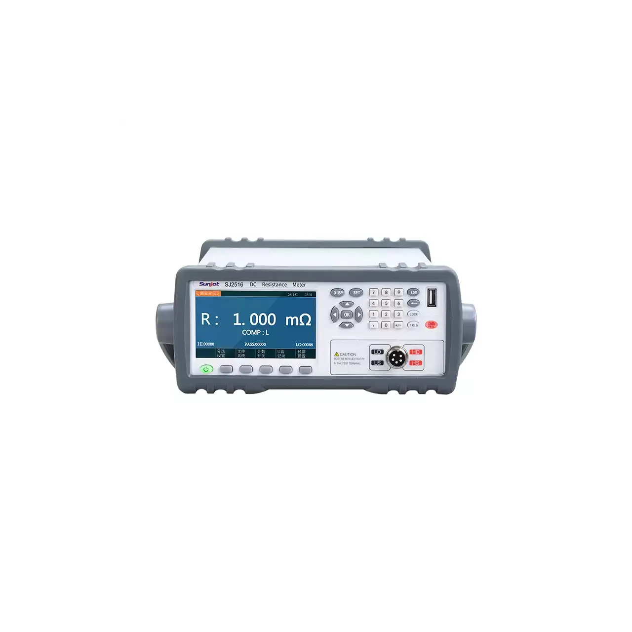
The instrument measures the DC resistance of three windings and displays them together. One model is listed, with three channels, a 240 × 128 dot-matrix display and a keypad that sets range, speed and comparator limits.
The front panel carries the display at the left, the keypad at the right and two circular connectors along the lower edge, with the power switch at the far right. The rear panel carries a 25-pin HANDLER connector, a fuse holder and the mains inlet. The case is 330 mm wide and about 5 kg, which is small enough to sit at the end of a motor assembly line rather than in a separate test room.
How the winding tester works
Each channel forces a DC current through one winding and senses the voltage across it through a separate pair of leads. Because the sense pair draws almost no current, the resistance of the leads and of the contact does not enter the result, which is what makes a reading in the tens of microhms meaningful.
The instrument selects a current range from eight available between 100 mA and 1 µA. The choice is a compromise: a large current gives a larger and more stable voltage across a low-resistance winding but heats it, while a small current avoids heating and leaves less signal. Automatic ranging makes that choice per winding; the locked mode holds a range so that three readings taken in sequence are directly comparable.
The three results are then shown as direct readings, as a percentage, or as a bin count. The percentage form is the one that matters for balance work, because it expresses each winding against a reference rather than leaving the operator to subtract two numbers. The comparator then turns the comparison into a same or different decision at the connector, and the buzzer reports pass or fail.
How to select the right winding tester
There is one model here, so the selection is really about fit rather than about choosing between variants. The first question is the resistance of the windings: a small appliance motor and a large industrial machine differ by decades, and the useful check is that the winding falls comfortably inside 10 µΩ to 2 MΩ rather than at the very edge of it.
The second is how the windings are brought out. Three channels only help if all three phases can be terminated at the fixture at the same time; a motor that arrives with a single lead pair per phase needs a lead set that reaches all three without moving clips between readings, otherwise the speed advantage disappears.
The third is what happens to the result. A bench that only wants a number can stop at the display. A bench that sorts needs the comparator and the HANDLER output; a bench that records needs RS232 or the PLC interface. The fourth is speed against stability: the four settings run from 30 readings per second down to 4, and a large winding that settles slowly is measured on the slower settings.
Send the winding resistance, the termination and the accept band, and the lead set and interface can be specified with the instrument.
Measurement limitations and selection considerations
The instrument measures resistance with a DC current, so it says nothing about insulation, inter-turn shorts or surge behaviour. A winding with a shorted turn can still show a plausible DC resistance, particularly on a large machine where one turn is a small fraction of the total; that fault belongs to a surge or impulse tester, not to this one.
Temperature is the other limit. Copper resistance rises with temperature, so three windings measured at different times after a run will differ even when they are identical. The percentage comparison is only as good as the assumption that all three readings were taken at the same temperature, which in practice means measuring before the motor has warmed up or allowing the same settling time for each.
Finally, the four-terminal connection removes lead resistance but not contact resistance at the winding terminal itself. A clip that sits on varnish rather than on bare copper will read high, and it will read high on whichever phase was clipped badly, which is exactly the pattern a balance test is meant to detect.
Every value below is taken from source documentation. Where a parameter is not stated in the available material it is marked as information required rather than estimated.