Electrical Test & Measurement · LCR Meters

Low-Inductance Pulse Coil Tester

Pulse winding tester for coils from 0.1 µH to 1 mH, with four-terminal sensing, voltage compensation, breakdown voltage analysis, a 200 MHz sampler and a fastest test time of 18 ms.

ZX8816 ·

Key specifications

Inductance range
0.1 µH to 1 mH
Peak test voltage
10 V to 1000 V
Voltage accuracy
±(1% of setting + 2.0 V)
Sampling
10 bits at 200 MHz, eight rate settings
Test pulses
1 to 32, with 0 to 9 excitation pulses
Fastest test time
18 ms at a single pulse
Detection modes
Area, area difference, jitter, corona second derivative, peak ratio, peak drop ratio and resonance area
Display
7-inch 65K colour TFT, 800 × 480
Interfaces
RS232 and HANDLER; USB host listed on the model card
Body
430 × 177 × 449.5 mm, 28 kg

A shorted turn is the fault that hides from every static measurement. Resistance moves by a fraction of a percent, low-frequency inductance barely changes, and the coil passes both tests before failing in service. The pulse test exists because it looks at the coil in motion rather than at rest.

Product overview

This is a single-model instrument for coils between 0.1 µH and 1 mH, with a peak test voltage from 10 V to 1000 V and a voltage accuracy of ±(1% of setting + 2.0 V). It samples at 200 MHz with 10-bit resolution and completes a single-pulse test in 18 ms.

The front panel carries a 7-inch 65K colour display with the waveform and the comparison result, a keypad at the right and the test connectors along the lower edge. The case is 430 mm wide and 28 kg, which is a bench instrument with a substantial charging supply inside it. Power draw is below 150 W with no load and below 1000 W when driving a test.

How the pulse coil tester works

A small capacitor is charged to the set voltage and discharged into the coil. The coil and the capacitor form a parallel resonant circuit, and the coil rings at its self-resonant frequency with an envelope that decays according to the losses in the winding and the core.

If one turn is shorted, that turn behaves as a coupled secondary with a low resistance across it. It draws energy out of the oscillation on every cycle, so the envelope collapses faster and the waveform shape changes. The instrument samples the decay, compares it with a stored reference from a known-good coil, and decides whether the difference exceeds the limits set for the chosen criterion.

The criteria matter because different faults show up differently. An area comparison catches a general loss of energy; an area difference comparison is more sensitive to a local change; jitter detection catches an unstable contact; the corona second derivative and the peak ratio criteria look for the high-frequency signature of a discharge. The breakdown voltage mode steps the voltage upward and applies the same comparison at each step, so the voltage at which the insulation starts to fail can be located rather than only detected.

How to select the right coil tester

The first question is the inductance. Below about 10 µH the oscillation is fast and the voltage across the part is small, and only an instrument with a fast sampler and four-terminal sensing will measure the coil rather than the leads. This model’s 0.1 µH lower limit is the reason it exists in the range.

The second is the test voltage. It has to be above the working voltage of the coil and below the level that damages a good one, and the stepped breakdown mode is how that level is found for a new design. A coil for a low-voltage converter and one for a mains filter need very different settings from the same instrument.

The third is the fault to be caught. A turn-to-turn short, a corona discharge and a partial discharge produce different signatures, and the detection mode has to match the fault. Running all seven criteria on every part is possible but slows the test and increases the chance of a false reject on a marginal coil.

The fourth is the fixture and the handling. A coil with fine wire and a small former needs a fixture that contacts it repeatably; the pulse test is sensitive to contact resistance in a way that a DC resistance measurement is not, because the contact sits inside the resonant circuit.

Measurement limitations and selection considerations

The test is comparative, not absolute. It says whether a coil differs from the reference, not what its inductance is, and a reference taken from a bad coil will pass bad coils. The reference has to be captured from a part that has been checked independently, and it has to be recaptured when the wire, the core or the winding machine changes.

The waveform depends on the fixture as much as on the coil. Lead length, contact pressure and the position of the coil in the fixture all change the ringing, which is why the fixture belongs to the test and why a coil measured in a different fixture is not comparable.

The test voltage is a compromise. A higher voltage finds more faults and stresses the insulation more; a lower one is safer and less sensitive. The stepped breakdown mode is destructive by design, so it is used on samples rather than on production parts.

Finally, the instrument charges a capacitor to a high voltage and discharges it into an inductor. The energy per pulse is small, but the current is not, and the interlock and grounding provisions on the rear panel are part of the safety of the test rather than an accessory to it.

Features

  • Four-terminal sensing, which on a coil below a microhenry removes most of the difference between the voltage at the instrument and the voltage across the part
  • Voltage compensation for inductance variation, so two coils that differ slightly in inductance are not rejected for that alone
  • A breakdown voltage analysis mode that steps the test voltage and compares the waveform at each step, locating the voltage at which the insulation begins to break down
  • A 200 MHz sampler with eight rate settings, which resolves the fast decay of a low-inductance coil that a slower sampler would miss
  • Seven detection criteria, so a fault can be caught by area, by area difference, by jitter, by corona or by peak shape depending on which one the part exhibits
  • Reference capture with averaging up to 32 waveforms, which produces a stable standard from a known-good coil
  • 18 ms test time at a single pulse, fast enough for a line that tests every coil
  • A demagnetising pulse before the measurement, so residual magnetism from the previous test does not shift the waveform

Technical specifications

Every value below is taken from source documentation. Where a parameter is not stated in the available material it is marked as information required rather than estimated.
Test output
Peak voltage10 V to 1000 VStandard
Voltage accuracy±(1% of the set voltage + 2.0 V)Standard
Inductance range0.1 µH to 1 mHStandard
Inductance range, alternate readingsGiven elsewhere in the material as 0.1 to 100 µH and as 1 µH to 1 mHInformation required
Test pulses1 to 32Standard
Excitation pulses0 to 9Standard
DemagnetisationA demagnetising pulse can be applied before the testStandard
Measurement connectionFour-terminal, to reduce the difference between the measured voltage and the voltage actually across the coilStandard
Voltage compensationCompensates for the voltage difference caused by inductance variation between coilsStandard
Acquisition
Sampler10 bits at 200 MHzStandard
Sample rate settingsEight, numbered 0 to 7Standard
Sampling, alternate readingGiven elsewhere as 100 MSa/s with 6500 bytes of storage per channel, upgradable to 200 MSa/sInformation required
Waveform display512 × 256 pointsStandard
AveragingUp to 32 reference waveforms averagedStandard
Automatic reference captureSelects the sampling rate automatically when capturing a referenceStandard
Waveform toolsVertical zoom, horizontal zoom and panStandard
Detection and output
Detection modesWaveform area, area difference, waveform jitter, corona second derivative, peak ratio, peak drop ratio and resonance area comparisonStandard
Detection modes, alternate readingDescribed elsewhere as four comparison methods: area, area difference, corona and phase differenceInformation required
Breakdown voltage analysisStart voltage, end voltage and voltage step are set, and the waveform is compared at each step against three criteriaStandard
Result indicationPass and fail by LED and buzzer, with different tones for eachStandard
Remote outputPass and fail through the EXT I/O and HANDLER portStandard
Interface, power and mechanical
InterfacesRS232 and HANDLERStandard
USBUSB host listed on the model card but not in the parameter tableInformation required
Storage, parameter tableInternal storage, plus 500 waveform files on a USB driveStandard
Storage, alternate reading500 files on a USB drive plus 50 internal, described together as 550Information required
Mains supply100 to 240 V AC, 50 or 60 HzStandard
Power consumptionBelow 150 W with no load; below 1000 W with a loadStandard
Dimensions430 mm × 177 mm × 449.5 mm, against 430 × 177 × 499.5 mm on the model cardInformation required
Weight28 kgStandard

Available models

Selection table
Model Configuration Key ranges Availability
ZX8816 Low-inductance pulse coil tester, 430 × 177 × 449.5 mm, 28 kg 0.1 µH to 1 mH; 10 V to 1000 V; 200 MHz sampler; 18 ms fastest test The only model described in detail in this material

Customization

  • Test fixtures for a particular coil former or a particular terminal arrangement
  • A handler connection for a line that sorts coils automatically
  • A higher sampling rate, which the material lists as an option on one of its summary pages

Certification and compliance

Certification documents not yet supplied

Certifications are only published once a certificate copy can be produced, so this section is deliberately empty rather than populated with assumed approvals. Tell us which approvals your application requires and we will confirm what is available for this instrument.

Parameters still to be confirmed

The following are required for a complete specification but are not stated in the documentation supplied to us. They are listed rather than estimated:

  • The correct inductance range, printed as 0.1 µH to 1 mH in the parameter table, as 0.1 to 100 µH in a feature page and as 1 µH to 1 mH on the main image
  • The correct dimensions, given as 430 × 177 × 449.5 mm in the parameter table and 430 × 177 × 499.5 mm on the model card
  • The correct sampling specification, given as 10 bits at 200 MHz in the parameter table and as 100 MSa/s with 6500 bytes per channel, upgradable to 200 MSa/s, elsewhere
  • The correct storage arrangement, given as internal storage plus 500 USB files in one place and as 200 internal plus 500 USB in another, with a third page describing 50 internal plus 500 USB as 550
  • Whether a USB host port is fitted, since the model card lists it and the parameter table does not
  • The number of detection modes, given as seven in the parameter table and as four comparison methods elsewhere
  • The pulse energy at 1000 V, which the material gives for the other models in the family but not for this one
  • Calibration certificate availability and standard
  • Warranty period and its terms

Frequently asked questions

What does a pulse test find that a resistance or inductance measurement does not?

A shorted turn. One shorted turn changes the DC resistance by a fraction of a percent and barely moves the inductance at low frequency, so both measurements can pass a faulty coil. In a pulse test the coil rings with a capacitor, and a shorted turn absorbs energy on every cycle of the oscillation, so the decay envelope collapses faster than the reference. The difference is visible in the waveform long before it is visible in a static measurement.

Why does a low-inductance coil need a different instrument from a motor winding?

Because the oscillation is fast and the voltage across the part is small. A coil of a fraction of a microhenry rings at a high frequency and decays in microseconds, so it needs a fast sampler and a connection that does not lose the signal in the lead impedance. The four-terminal sensing and the 200 MHz sampler exist for that case; a tester built for a large motor winding samples too slowly and measures the leads as much as the coil.

What has to be confirmed before a quotation?

The inductance and the number of turns of the coil, the test voltage the insulation has to withstand, the fault the test is meant to catch — a shorted turn, a corona discharge or a partial discharge — and how the coil is presented to the fixture. Those answers fix the voltage range, the detection mode and the fixture.

Related products

Other models in the same range

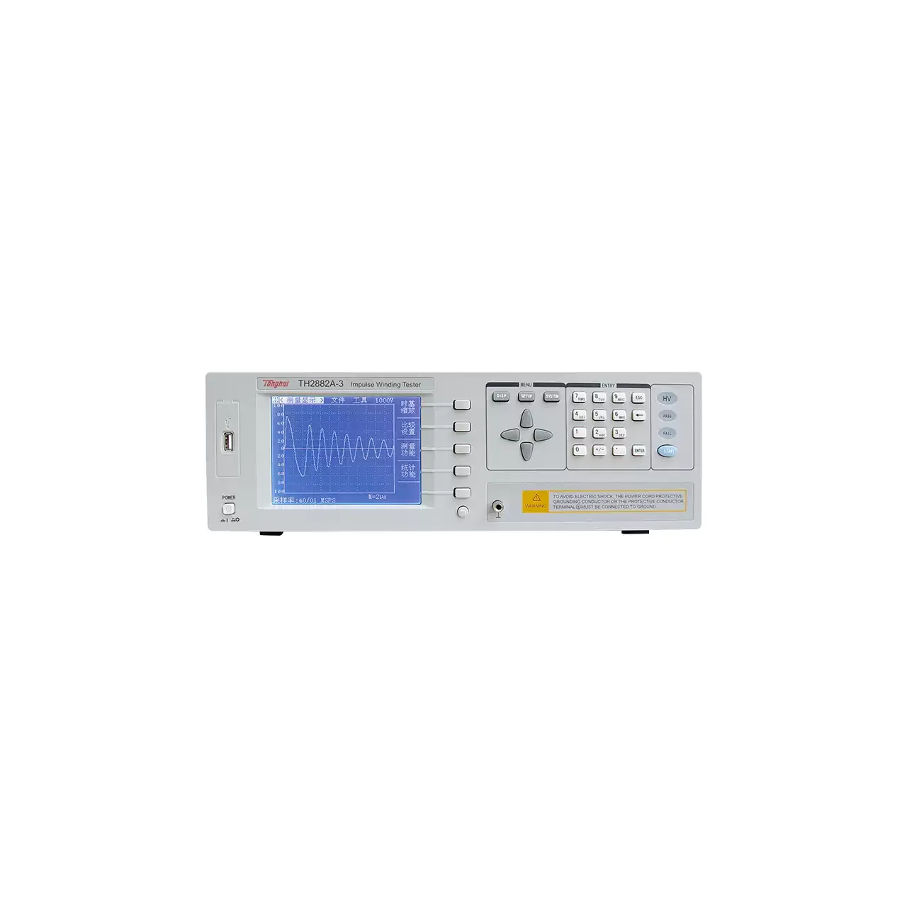
Bench impulse winding tester in a light grey case, with a colour LCD at the left showing a damped oscillatory waveform and two readings below it, a column of four soft keys beside the screen, a keypad and three status keys at the right, and a USB socket at the far left

TH2882A-3 (3 models) · LCR Meters

Impulse Winding Tester

Impulse winding testers that apply a high-voltage pulse to a coil and compare the response waveform against a reference, for finding inter-turn shorts, weak insulation and winding faults in single-phase and three-phase parts.

Output pulse voltage
300 V to 3000 V ±5% in 50 V steps on TH2882A-3; 500 V to 5000 V ±5% in 100 V steps on TH2882A-5; the model list gives the same 500 V to 5000 V for TH2882AS-5
Pulse energy
≤90 millijoules on TH2882A-3; ≤250 millijoules on TH2882A-5 and, in the model list, on TH2882AS-5
Inductance range
≥10 µH on TH2882A-3; ≥20 µH on TH2882A-5; ≥200 µH on TH2882AS-5
Waveform sampling
≤40 MSPS at 8 bit
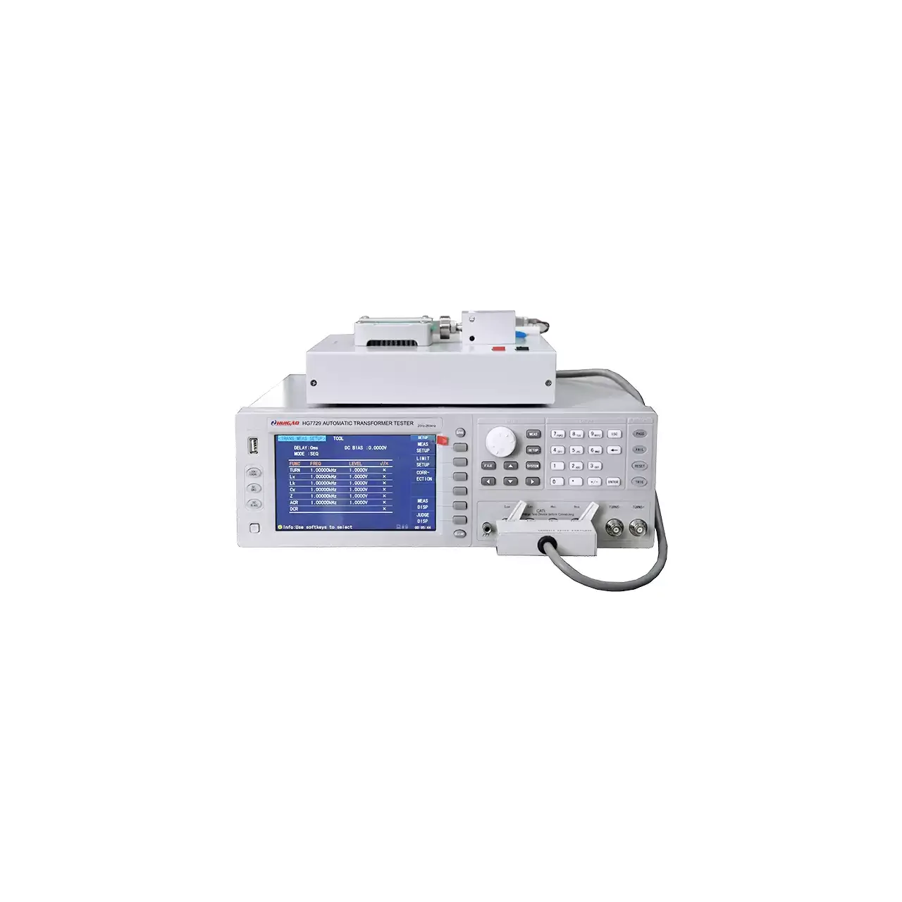
Bench transformer tester in a light grey case, with a colour LCD at the left listing turns ratio, inductance, leakage inductance and resistance readings, a column of soft keys and a numeric keypad at the right, and a test fixture resting on top of the case connected to the front panel by a ribbon cable and two coaxial leads

HG7729 (4 models) · LCR Meters

Transformer Comprehensive Tester

Four transformer testers with 20-channel scanning, LCR and DC resistance measurement at 0.05% basic accuracy, built-in DC bias and test frequencies from 20 Hz to 1 MHz for production testing of wound components.

Test frequency
20 Hz to 200 kHz on HG7729; 20 Hz to 300 kHz on HG7729A and HG7729B; 20 Hz to 1 MHz on HG7729C
Scanning
20-channel transformer scan on all four models
LCR parameters
|Z|, |Y|, C, L, X, B, R, G, D, Q and phase, plus DC resistance, turns and phase
Transformer scan parameters
Turns ratio, number of turns, phase, inductance, capacitance, leakage inductance, quality factor, AC resistance, DC resistance, balance, pin short and LED

Request a quotation for the ZX8816

Send the configuration you need and we will confirm availability, lead time and terms. Minimum order quantity is 1 pc.

Request for quotation

Request a quotation - ZX8816

Send the technical detail and we will confirm availability, lead time and terms. In-stock items ship within 48 hours; customized specifications typically take 2-10 days. Minimum order quantity is 1 pc.

The more of this you can give us, the fewer exchanges are needed before we can quote.
No file chosen
Datasheet, drawing, BOM or photograph. One file, up to 10 MB (PDF, Office, image or ZIP).

By submitting this form you agree that we may contact you about this enquiry. We do not sell or share enquiry data. See our privacy policy.

Items held in stock are dispatched within 48 hours of order confirmation. Customized specifications are produced to order and typically ship within 2 to 10 days. Transit time then depends on the shipping method and destination.

Request a Quote WhatsApp