Electrical Test & Measurement · LCR Meters

Impulse Winding Tester

Impulse winding testers that apply a high-voltage pulse to a coil and compare the response waveform against a reference, for finding inter-turn shorts, weak insulation and winding faults in single-phase and three-phase parts.

TH2882A-3 (3 models) ·

Key specifications

Output pulse voltage
300 V to 3000 V ±5% in 50 V steps on TH2882A-3; 500 V to 5000 V ±5% in 100 V steps on TH2882A-5; the model list gives the same 500 V to 5000 V for TH2882AS-5
Pulse energy
≤90 millijoules on TH2882A-3; ≤250 millijoules on TH2882A-5 and, in the model list, on TH2882AS-5
Inductance range
≥10 µH on TH2882A-3; ≥20 µH on TH2882A-5; ≥200 µH on TH2882AS-5
Waveform sampling
≤40 MSPS at 8 bit
Input impedance
10 MΩ resistive divider
Comparison methods
Area, area difference, corona discharge and phase difference
Display
320 × 240 dot LCD with a 240 × 200 dot waveform area; a 480 × 272 TFT panel is also listed for TH2882A-3
Measurement speed
5.5 per second with the waveform off and 3.3 with it on, for the two single-phase models; 2.0 and 1.5 per second for TH2882AS-5
Waveform storage
60 reference waveforms inside the instrument and 500 on a USB drive
Interface
RS232C, USB HOST and HANDLER as standard, GPIB optional

A turn-to-turn short inside a coil can leave the inductance almost unchanged and the resistance untouched, which is why a winding that passes a resistance and an inductance check can still fail in service. An impulse test looks at the winding as a distributed network and judges the shape of its response.

Product overview

The range contains three instruments that share one method and differ in what they can drive. Two are single-phase machines that step up in pulse voltage and energy; the third is a three-phase instrument for stators and three-phase windings, and it needs a larger inductance before it can test at all.

All three store reference waveforms, compare a measured response against them, and return a pass or fail. The differences that matter in selection are the voltage the pulse reaches, the energy it delivers, and the number of phases the fixture has to contact.

How the impulse winding tester works

The instrument charges a capacitor and discharges it into the winding under test. The winding responds with a damped oscillation whose frequency and decay are set by its inductance, its distributed capacitance and the losses inside it. That response is digitised at high speed and stored as a waveform.

A known-good winding is measured first and its waveform is kept as the reference. Every part tested afterwards is compared against it. A short between two turns reduces the effective number of turns and changes the resonant behaviour of the network, so the two waveforms separate even where a single inductance reading would not.

The comparison can be made in several ways. Area comparison looks at the integral of the difference between the curves; area difference compares the areas under each; phase difference watches where the peaks fall in time; and corona comparison looks for the high-frequency burst that a partial discharge produces. Each method is sensitive to a different fault, which is why the instrument offers all four rather than one.

The voltage control mode matters here. In normal mode the instrument sets the open-circuit voltage, and a low-impedance winding pulls the actual pulse down. In constant mode the output is regulated so that the winding does not change the applied stress, which keeps the test comparable between parts of different impedance.

How to select the right impulse winding tester

Start with the part. A single-phase coil, a solenoid or a small transformer winding belongs on one of the single-phase models; a stator or a three-phase winding needs the three-phase instrument, because the test has to be applied across the phase pairs and compared in the same configuration.

Then set the voltage from the insulation the winding is built to withstand, not from the highest the instrument can produce. A pulse above what the insulation can take will damage good parts, and the damage may not appear until the part is in service.

Then check the energy and the inductance. A large winding needs more energy to reach the test voltage, and the instrument’s inductance floor has to be below the part being tested, or the response is too small to judge. The three models step up in both figures together.

Then decide how the instrument is operated. A bench with a foot switch and a fixture is one pattern; a line that sorts parts needs the handler interface and the pass and fail outputs; a line controlled by a computer needs the serial port, and the bus interface if that is what the controller speaks.

Send the winding drawing, the number of phases, the inductance and the insulation class, and a model, a lead and a fixture can be quoted against them.

Measurement limitations and selection considerations

The test compares a part against a reference, so the reference has to be right. A waveform stored from a marginal winding will pass marginal parts, and a reference taken at a different voltage or in a different fixture is not the same test.

The method is sensitive to the fixture as much as to the winding. Lead length, contact position and the capacitance of the jig are part of the network being measured, so a part that passes on one fixture can fail on another. The reference and the production parts have to be measured the same way.

The pulse is a stress, not a proof. A part that survives the test has survived that pulse; whether it survives the insulation test that follows, or the voltage in service, is a separate question.

Finally, the inductance floor is a real limit. Below the minimum the response is dominated by the fixture and the comparison loses meaning, which is why a small winding may need a different instrument rather than a different setting.

Features

  • A high-voltage pulse is compared against a stored reference waveform rather than against a single number, so a fault shows up as a change in shape rather than as a threshold that has to be guessed
  • Four comparison criteria are provided, which allows the same instrument to judge a gross short, a partial discharge and a subtle phase shift with the method that suits each
  • Two voltage control modes: one sets the open-circuit voltage, the other regulates the pulse so that the impedance of the winding does not change the applied stress
  • Waveforms are captured at high speed and eight-bit resolution, which is what preserves the fast edges that carry the information about inter-turn insulation
  • Foot-switch, internal, external and bus triggering, so the instrument can be operated at a bench, from a fixture or from a production line controller
  • Sixty reference waveforms held in the instrument and more on a USB drive, so a product changeover does not require the reference part to be found again
  • Pass and fail indication with an alarm output, and a handler interface for sorting

Technical specifications

Every value below is taken from source documentation. Where a parameter is not stated in the available material it is marked as information required rather than estimated.
Pulse output
Output voltage, TH2882A-3300 V to 3000 V ±5%, in 50 V stepsStandard
Output voltage, TH2882A-5500 V to 5000 V ±5%, in 100 V stepsStandard
Output voltage, TH2882AS-5Not stated in the parameter table; the model list gives 500 V to 5000 V ±5% in 100 V stepsInformation required
Voltage controlNormal mode sets the open-circuit voltage at the test terminals; constant mode regulates the voltage so that the winding impedance does not change itStandard
Pulse energy, TH2882A-3≤90 millijoulesStandard
Pulse energy, TH2882A-5≤250 millijoulesStandard
Pulse energy, TH2882AS-5Not stated in the parameter table; the model list gives ≤250 millijoulesInformation required
Inductance range, TH2882A-3≥10 µHStandard
Inductance range, TH2882A-5≥20 µHStandard
Inductance range, TH2882AS-5≥200 µHStandard
Measurement
Test range, TH2882A-3Single phaseStandard
Test range, TH2882A-5Single phase in the parameter table; three-phase three-wire and three-phase four-wire in the model list and on the case marking; blank in the comparison tableInformation required
Test range, TH2882AS-5Three-phase three-wire and three-phase four-wireStandard
Sampling rate≤40 MSPS, 8 bitStandard
Input impedance10 MΩ, resistive dividerStandard
Measurement speed, TH2882A-3 and TH2882A-55.5 per second with the waveform display off; 3.3 per second with it onStandard
Measurement speed, TH2882AS-52.0 per second with the waveform display off; 1.5 per second with it onStandard
Repeatability±1%Standard
Waveform measurementsVoltage, time and frequency, read from the displayed waveformStandard
Comparison and display
Comparison methodsArea comparison, area difference comparison, corona discharge and phase differenceStandard
Trigger modesInternal, manual by foot switch, external and busStandard
Display, parameter table320 × 240 dot LCD with a 240 × 200 dot waveform areaStandard
Display, TH2882A-3 summaryA 320 × 240 dot graphic LCD and a 480 × 272 dot TFT LCD are both listed in the same summaryStandard
Display contentSettings, the reference and measured waveforms, and the measurement and comparison result, in English and ChineseStandard
Judgement outputPass and fail indication with an alarm outputStandard
Storage and interface
Internal storage60 reference waveformsStandard
USB storage500 reference waveforms on a USB drive; the same port is used for firmware updatesStandard
Standard interfaceRS232C, USB HOST and HANDLERStandard
Optional interfaceGPIBOptional
Rear panelHANDLER and RS-232C connectors, ground terminal and fuse holderStandard
Mechanical
Dimensions400 mm wide × 132 mm high × 385 mm deep, measured on the TH2882A-3 caseStandard
Weight7.5 kg, measured on the TH2882A-3 caseStandard
Dimensions and weight, TH2882A-5 and TH2882AS-5Not stated in the materialInformation required
Supplied leadTH2883-01 high-voltage test lead, listed for TH2882A-3 and TH2882A-5Standard
Supplied lead, TH2882AS-5Not stated in the materialInformation required

Available models

Selection table
Model Configuration Key ranges Availability
TH2882A-3 Single-phase, 400 × 132 × 385 mm, 7.5 kg, up to 3000 V in 50 V steps Pulse energy ≤90 millijoules; inductance ≥10 µH; 5.5 or 3.3 tests per second The 3 kV single-phase model
TH2882A-5 Up to 5000 V in 100 V steps Pulse energy ≤250 millijoules; inductance ≥20 µH; test range printed as single phase in the parameter table and as three-phase in the model list The 5 kV model, with the wider energy and inductance window
TH2882AS-5 Three-phase three-wire and three-phase four-wire Inductance ≥200 µH; 2.0 or 1.5 tests per second; pulse voltage and energy given only in the model list The three-phase model, for stators and three-phase windings

Customization

  • GPIB interface as an option where the production line already uses that bus
  • TH2883-01 high-voltage test lead, listed for the two single-phase models
  • Foot switch for manual triggering at a bench
  • Test fixtures for a particular stator or bobbin, since a wound part is normally contacted by a jig

Certification and compliance

Certification documents not yet supplied

Certifications are only published once a certificate copy can be produced, so this section is deliberately empty rather than populated with assumed approvals. Tell us which approvals your application requires and we will confirm what is available for this instrument.

Parameters still to be confirmed

The following are required for a complete specification but are not stated in the documentation supplied to us. They are listed rather than estimated:

  • The test range of TH2882A-5, which the parameter table gives as single phase, the model list as three-phase three-wire and three-phase four-wire, and the comparison table as blank
  • The output pulse voltage and pulse energy of TH2882AS-5, which are blank in the parameter table and given only in the model list
  • Whether the display is a 320 × 240 dot LCD or a 480 × 272 dot TFT panel, both of which appear in the TH2882A-3 summary
  • Dimensions and weight of TH2882A-5 and TH2882AS-5
  • The test lead supplied with TH2882AS-5, which the material does not name
  • Whether GPIB is fitted as standard on any model or always an option
  • Whether a calibration certificate is supplied and to which standard
  • Warranty period and its terms
  • Working temperature range and ingress protection
  • The full packing list, of which only the high-voltage lead is named

Frequently asked questions

What is the difference between the three models?

The two single-phase models differ in pulse voltage and energy: the 3 kV model steps in 50 V increments with a smaller energy limit, the 5 kV model steps in 100 V with a larger one and needs a larger inductance to test. The third model is the three-phase instrument, which tests three-wire and four-wire windings and needs a larger inductance again. The material also lists a single-phase test range for the 5 kV model in one table and a three-phase range in another, so that point should be confirmed before ordering.

Why compare waveforms instead of measuring inductance?

An inductance reading averages the whole winding into one number, so a short between two turns of a large coil can disappear inside the tolerance. A pulse applied across the winding produces a response whose shape depends on the distributed capacitance and inductance of every turn; a fault changes that shape, and the comparison against a known-good part exposes it.

What has to be confirmed before a quotation?

The winding type and whether it is single-phase or three-phase, the inductance and the test voltage the procedure calls for, the pulse energy the insulation can take without damage, and how the instrument is triggered and read on the line. Those answers fix the model, the lead and the fixture.

Related products

Other models in the same range

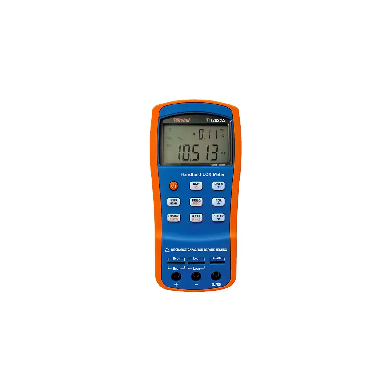
Hand-held LCR meter with an orange and blue case, shown from the front with the backlit display at the top showing a secondary and a primary reading, eight keys and a power button below it, and a five-terminal test slot above three banana sockets at the bottom

TH2822A (4 models) · LCR Meters

Handheld LCR Meter

Four handheld LCR meters covering 100 Hz to 100 kHz, with 0.25% or 0.1% basic accuracy, a dual parameter backlit display, automatic range and Mini-USB control, for measuring inductors, capacitors and resistors away from the bench.

Test frequencies
100 Hz, 120 Hz, 1 kHz and 10 kHz; 100 kHz added on TH2822C and TH2822E
Basic accuracy
0.25% on TH2822A and TH2822C; 0.1% on TH2822D and TH2822E
Measured parameters
L, C, R and Z as primary, with D, Q, phase angle and ESR as secondary; DC resistance on TH2822D and TH2822E
Display ranges
L 0.00 µH to 1000.0 H; C 0.00 pF to 20.000 mF; Z and R 0.0000 Ω to 10.000 MΩ
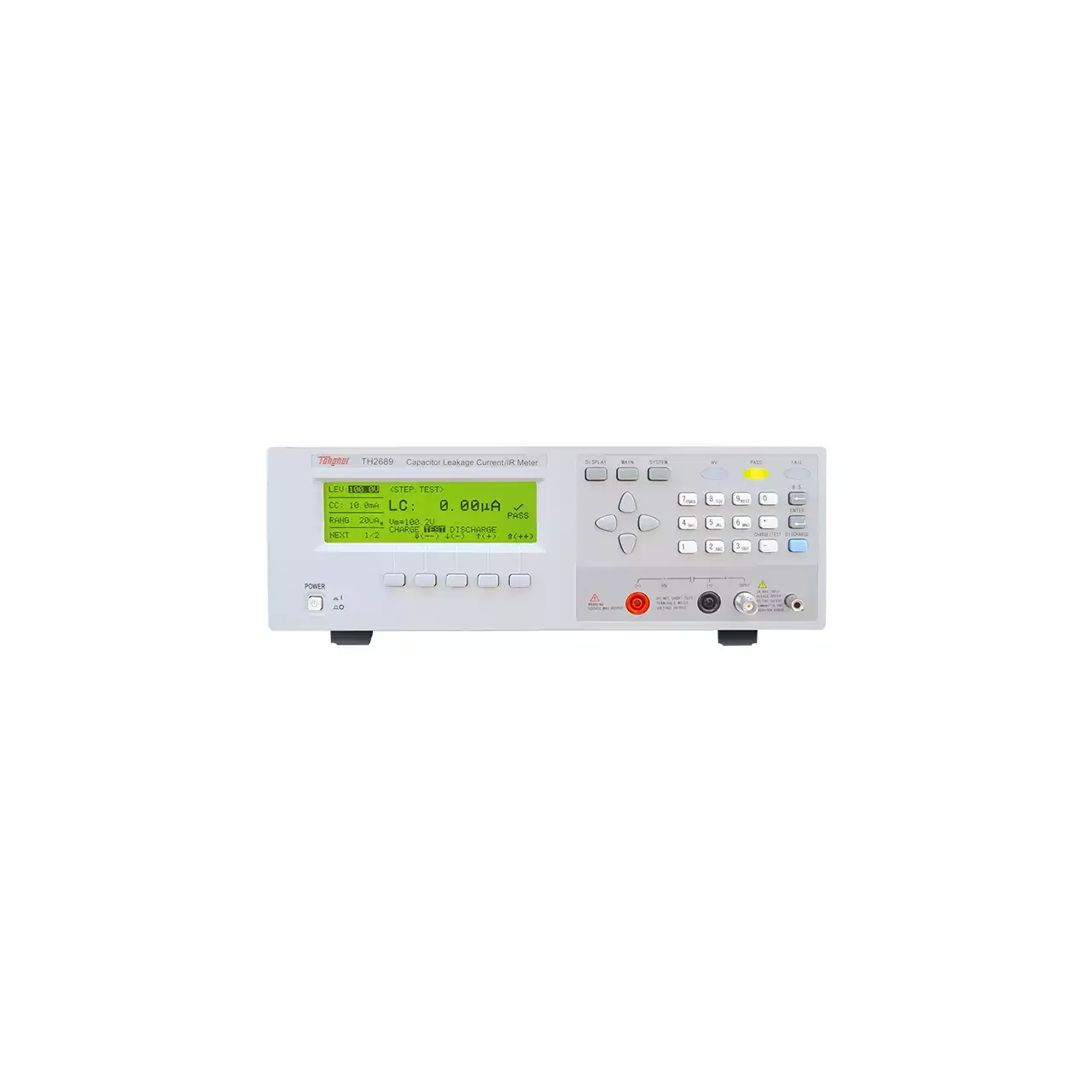
Bench capacitor leakage tester in a light grey case, with a backlit dot matrix display at the left showing a leakage current reading and charge status, function keys and a numeric keypad at the right, and a red high-voltage terminal beside two measurement terminals at the lower right

TH2689 (4 models) · LCR Meters

Capacitor Leakage Current Tester

Bench capacitor leakage testers with adjustable test voltage, leakage current measurement down to the nanoamp region, insulation resistance to 99.99 GΩ, timed charging and comparator limits.

Test voltage
1 V to 800 V on TH2689; 1 V to 500 V on TH2689A; 0 to 200 V and 0 to 500 V on TH2686N and TH2686C
Voltage accuracy
±(0.5% of setting + 0.2 V) on TH2689 and TH2689A; ±1% of setting + 1 digit on TH2686N
Leakage current range
0.001 µA to 20.00 mA on TH2689 and TH2689A; 10 nA to 19.99 mA with 1 nA resolution on TH2686N; 0 to 30 mA in 10 ranges on TH2686C
Insulation resistance
0.01 MΩ to 99.99 GΩ on TH2689 and TH2689A

Request a quotation for the TH2882A-3

Send the configuration you need and we will confirm availability, lead time and terms. Minimum order quantity is 1 pc.

Request for quotation

Request a quotation - TH2882A-3

Send the technical detail and we will confirm availability, lead time and terms. In-stock items ship within 48 hours; customized specifications typically take 2-10 days. Minimum order quantity is 1 pc.

The more of this you can give us, the fewer exchanges are needed before we can quote.
No file chosen
Datasheet, drawing, BOM or photograph. One file, up to 10 MB (PDF, Office, image or ZIP).

By submitting this form you agree that we may contact you about this enquiry. We do not sell or share enquiry data. See our privacy policy.

Items held in stock are dispatched within 48 hours of order confirmation. Customized specifications are produced to order and typically ship within 2 to 10 days. Transit time then depends on the shipping method and destination.

Request a Quote WhatsApp