- Bias current
- 0 to 12 A, 0 to 25 A, or up to 225 A with eight slaves stacked
- Current resolution
- 0.25 mA on the lowest range
- Maximum output voltage
- 11 V at every current setting
- Bridge frequency
- 50 Hz to 200 kHz as standard; to 1 MHz or 2 MHz on the wide-band models
- Basic accuracy
- 0.05% on the bridge
- Reading speed
- Up to 50 readings per second above 1 kHz
- Sweep
- Single current or stepped sweep, with an adjustment time from 4 ms to 3600 s
- Display
- 7-inch LCD, with LED indicators on the slave unit
- Interfaces
- RS232C, USB host, USB device and HANDLER; GPIB optional on the 25 A models
- Body
- 400 × 135 × 465 mm at 9.9 kg, or 430 × 178 × 465 mm at 19 kg
An inductor measured without current is a different component from the one that sits in a switching supply. The core is unmagnetised, the inductance looks comfortable, and nothing in the reading warns that the part will saturate at half its rated load. A bias bridge exists to close that gap.
Product overview
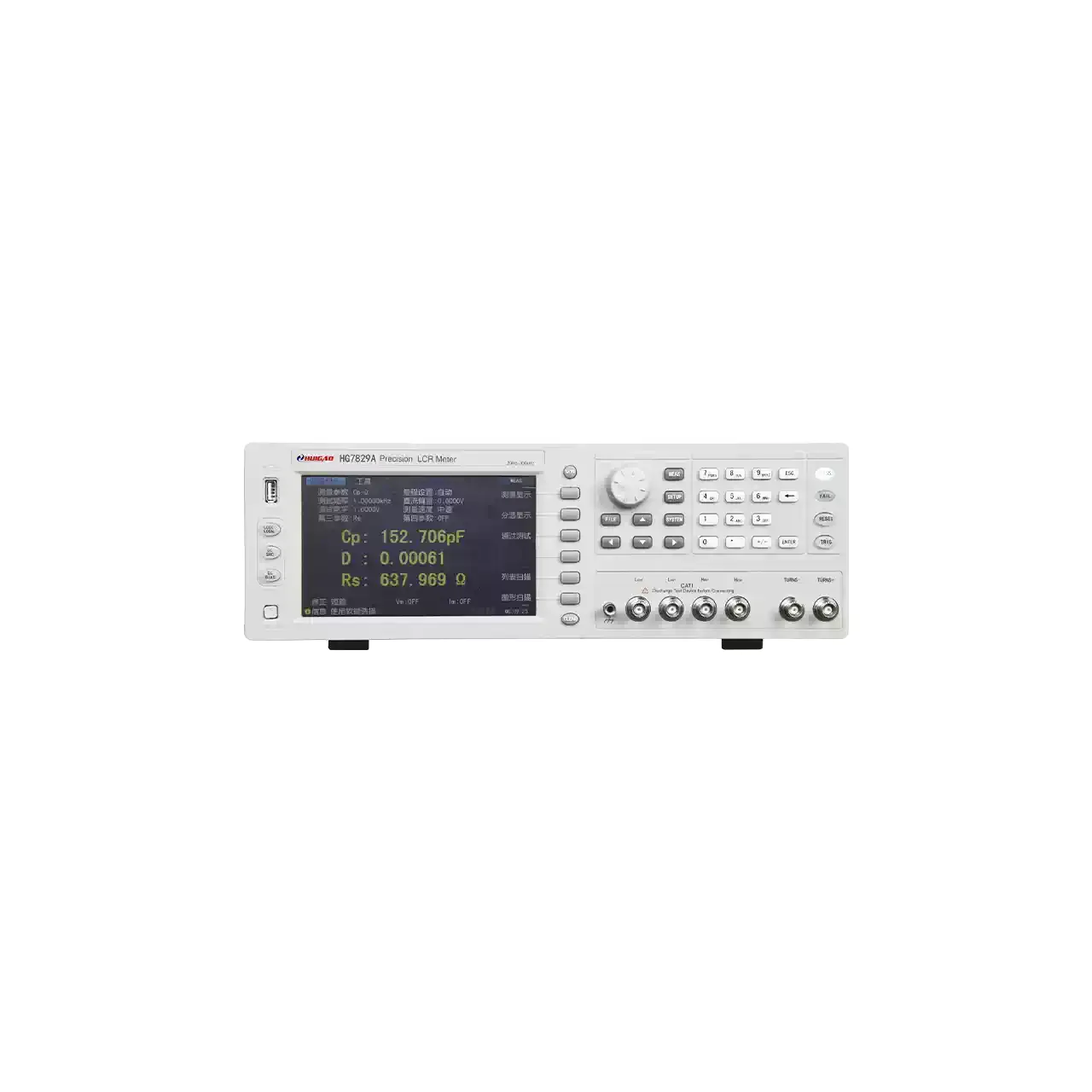
These instruments put a high-frequency LCR bridge and a regulated DC current source in one case. The 12 A family covers 0 to 12 A with a 0.25 mA step; the 25 A family covers 0 to 25 A; and the ZX1379 master can drive up to eight slaves for 225 A. Compliance is 11 V at every current setting.
The bridge itself covers 50 Hz to 200 kHz as standard, with 500 kHz, 1 MHz and 2 MHz versions available, and the ZX1379 family starts at 20 Hz. Basic accuracy is 0.05% and the reading rate reaches 50 per second above 1 kHz. The 12 A models are 400 mm wide at 9.9 kg; the 25 A models are 430 mm wide at 19 kg.
How the bias bridge works
The current source forces a regulated direct current through the winding, and the bridge superimposes its small high-frequency signal on top of it. The bridge measures the voltage across the component and the current through it at that frequency, separates the two into in-phase and quadrature components, and derives inductance and the loss terms from them.
The difficulty is that the bridge has to see a millivolt-level signal while the source is driving amps through the same winding. That is why the current source is built into the instrument rather than added outside: the coupling, the grounding and the settling are handled inside one chassis, and the sweep can step the current and read the bridge at each step without an external controller.
The sweep is the working mode. A start current, an end current and a step are set, the instrument dwells at each point for an adjustable time between 4 ms and 3600 s, and the inductance is recorded. The dwell matters because a large core does not settle instantly after the current changes; too short a delay reads the transient rather than the steady value.
How to select the right bias bridge
The first question is the current and the winding resistance together. Compliance is 11 V, so the maximum current a winding can actually reach is 11 V divided by its DC resistance; a 2 Ω winding will not go past 5.5 A whatever the instrument is rated at. Both numbers are needed before the model is chosen.
The second is the frequency at which the inductance has to be measured. A part for a 100 kHz converter needs a bridge that reaches 100 kHz; one for a 1 MHz converter needs the wide-band version. This is independent of the current, and the two choices multiply the model count.
The third is whether the current has to be stacked. A single 25 A unit covers most power-supply chokes; a traction or inverter component may need 100 A or more, which is the ZX1379 route with slaves.
The fourth is the dwell time and the interface. A small core settles in milliseconds, a large one may need seconds, and the sweep time range covers both. If the instrument is part of a line, the SCPI command set, the handler port and the stored files decide how it is integrated.
Measurement limitations and selection considerations
The source delivers current, and that current heats the winding. Copper resistance rises with temperature, and a core that has been held at 25 A for a long time will not read the same as one measured cold. The material quotes 2 to 3 hours of continuous full-current output as a conservative limit, which is a statement about the instrument rather than about the component; the component’s own heating still has to be managed in the test procedure.
The 11 V compliance is the hard limit on what can be driven. A long winding with thin wire may have enough resistance that the set current is never reached, and the instrument will sit at its voltage limit instead. That is a property of the load, not a fault, and it has to be checked with the actual resistance before the model is ordered.
A bias sweep describes the core at DC. It does not show the core loss at the switching frequency, and it does not reproduce the minor hysteresis loops a converter actually traverses. Where loss is the quantity of interest, a different measurement is needed.
Finally, the reading depends on the dwell time and on the recent history of the core. A sweep run upwards from zero and a sweep run downwards from saturation will not trace the same curve, which is why the direction of the sweep belongs in the test procedure alongside the step and the dwell.
Every value below is taken from source documentation. Where a parameter is not stated in the available material it is marked as information required rather than estimated.