- Test frequency
- 100 Hz to 200 kHz in 37 points on HG2776A; 100 Hz to 10 kHz in four points on HG2775A
- Basic accuracy
- 0.05% on HG2776A; 0.1% on HG2775A
- Test level
- 10 mV to 2.00 V in 10 mV steps on HG2776A; 0.1 V, 0.3 V or 1 V on HG2775A
- Inductance range
- 0.01 nH to 9999.99 H
- Impedance range
- 0.1 mΩ to 99.9999 MΩ
- Ranging
- Automatic or manual; nine ranges on HG2776A, five on HG2775A
- Sorting
- Ten bins on HG2776A; four bins on HG2775A
- Display
- 240 × 128 dot-matrix LCD with soft keys
- Interface
- PLC and RS232 optional on both
- Body
- 330 × 320 × 120 mm, about 5 kg
An inductor is the one passive component whose value is least like a constant. It moves with frequency, with drive level and with the core, so a meter that reports a single number at a single condition is telling the buyer very little. The useful question is whether the instrument can reproduce the condition the datasheet was written at.
Product overview
Two models share one chassis and one display. HG2776A covers 100 Hz to 200 kHz in 37 points with a level settable in 10 mV steps and 0.05% basic accuracy; HG2775A covers four points between 100 Hz and 10 kHz with three fixed levels and 0.1%.
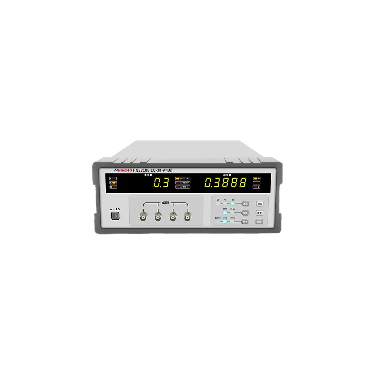
Both use a 240 × 128 dot-matrix LCD with soft keys down the side of the screen and a numeric keypad at the right, and both bring the measurement out to a four-terminal connection along the lower front edge. The case is 330 mm wide and about 5 kg, with the mains switch at the lower right and a fuse holder and voltage selector on the rear panel.
How the inductance meter works
The instrument drives the winding with a sine wave at the selected frequency and measures the voltage across it and the current through it. Those two signals are resolved into an in-phase and a quadrature component, and their ratio gives impedance and phase. From those, the instrument derives inductance and the loss terms that describe how far the part is from an ideal inductor.
Because a real winding behaves differently depending on how it is modelled, the result is offered in series or parallel form. A low-loss inductor measured in series and the same part measured in parallel will not give the same numbers, and the datasheet normally states which form it uses. The parameter list reflects that: LP-D and LS-D are the same quantity in two equivalent circuits, and the instrument shows the pair that matches the model in use.
The four-terminal connection is what makes a low-impedance reading credible. Two leads carry the drive current and two sense the voltage at the terminals, so the resistance of the leads and of the contact does not appear in the result. Open and short zeroing then removes what remains of the fixture.
How to select the right inductance meter
The first question is the frequency. If the part is specified at a point inside 100 Hz to 10 kHz, HG2775A can reproduce it. If the datasheet quotes 100 kHz, or quotes a curve that has to be checked at several points, only HG2776A can be set there.
The second is the drive level. A core measured at a low level sits on a different part of its magnetisation curve than the same core at a high level, and a meter with three fixed levels cannot explore that. The 10 mV step on HG2776A is the reason to choose it even when the frequency is low.
The third is throughput and sorting. HG2776A reads at up to 32 per second and sorts into ten bins; HG2775A reads at up to 17 per second and sorts into four. A line that grades parts into several tolerance bands needs the larger bin count; a bench that only accepts or rejects does not.
The fourth is how the part is contacted. A wound component with thick leads and a low inductance needs a fixture that holds the terminals at a fixed spacing, because the loop area of the connection is part of what is being measured.
Measurement limitations and selection considerations
The instrument measures a small-signal inductance at a selected frequency and level. It does not test the saturation behaviour of a core, and it does not apply a direct bias current, so a choke specified at its working current cannot be characterised on this meter without external bias equipment.
The connecting leads are part of the circuit at high frequency. Two long leads run to a small inductor add their own inductance, and no amount of zeroing removes an effect that changes with the position of the leads. A fixture that holds the part at a repeatable spacing is worth more than a better accuracy figure in that situation.
Temperature and recent history also matter. A core that has been driven hard retains a magnetisation state, and the first reading after a part is connected can differ from the second. Reading the part twice, or deglitching the core before the measurement, is standard practice where the inductance is small and the tolerance tight.
Finally, the reading is only comparable with another reading taken under the same conditions. Two meters of the same model at different levels, or the same meter before and after a fixture change, will not agree to the last digit, which is why the setup belongs in the test procedure and not in the operator’s memory.
Every value below is taken from source documentation. Where a parameter is not stated in the available material it is marked as information required rather than estimated.