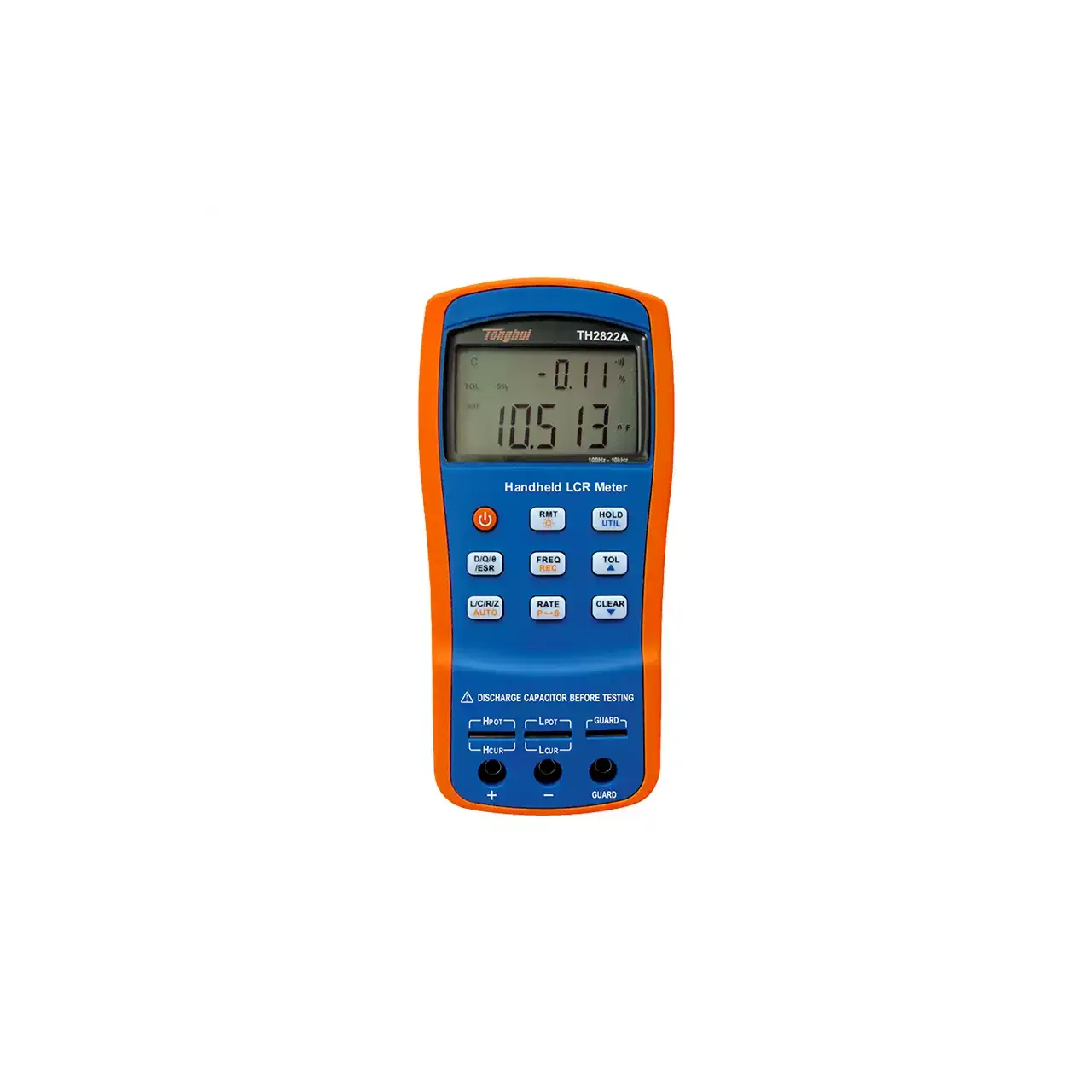
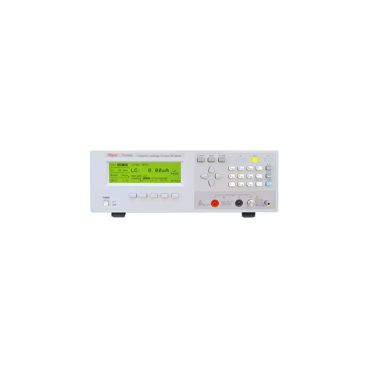
- Test frequencies
- 100 Hz, 120 Hz, 1 kHz and 10 kHz on the general models; up to 100 kHz on HG2817 and HG2817B; 8 points to 100 kHz on HG2817D; 37 points from 50 Hz to 200 kHz on HG2817A
- Basic accuracy
- 0.10% on the general models; 0.05% on HG2816A and HG2817A
- Test level
- 0.3 V on HG2810B; 0.1 V, 0.3 V or 1.0 V on most other models; 10 mV to 2.00 V in 10 mV steps on HG2816A and HG2817A
- Display ranges
- L 0.01 µH to 99999 H and C 0.01 pF to 99999 µF on the general models, with wider ranges on the LCD models
- Measurement speed
- 5, 15 or 25 per second on HG2810B and HG2810; 5, 8 or 17 on HG2810A and HG2817D; 2, 5 or 10 on HG2817B; 3, 5.5, 11 or 32 on HG2817A
- Sorting
- Four bins on most models, ten bins on HG2817A, none on HG2810B and HG2817B
- Interface
- RS232 and HANDLER optional on most models and standard on HG2817A; no interface on HG2810B; USB on the upgraded models
- Terminals
- Five-terminal, defined as HD current high, LD current low, HS voltage high and LS voltage low
- Body
- 335 × 325 × 105 mm at 5.0 kg on HG2810B and HG2810; up to 370 × 320 × 130 mm, 5.0 kg on HG2817B
An incoming inspection lives or dies on whether the instrument measures at the frequency the part was specified at. This range runs from a three-frequency bench bridge to a wide-band model with a programmable level, and the differences between them are almost entirely about that.
Product overview
Nine models sit in one family, and they divide into two groups. The general models use a handful of fixed test frequencies and a fixed set of levels; the wide-band models sweep a continuous range and allow the level to be set in small steps. Within each group, the models step up in display type, parameter set, sorting and interface.
That structure is deliberate: the same measurement engine appears at several levels of fit-out, so a bench can be bought at the level it needs rather than at the top of the range. The trap is to buy by display size or by bin count when the decision should start from the frequency.
How the LCR bridge works
The instrument applies an alternating signal to the component and measures the voltage across it and the current through it, separating the two into an in-phase and a quadrature component. The ratio gives impedance, and the phase angle separates resistance from reactance; from those the instrument derives inductance or capacitance and the loss terms that describe the part.
The connection is four-terminal, brought out on five terminals because the screen is carried separately. Two terminals carry the current, two sense the voltage at the component, and the sense pair draws almost no current, so the resistance of the leads and of the contact does not enter the result. That is what allows a milliohm-level reading to mean anything.
Because every result belongs to the frequency and level at which it was taken, the instrument states both, and the wide-band models exist so that a datasheet value taken at an arbitrary frequency can be reproduced rather than approximated.
How to select the right LCR bridge
Begin with the specification the parts are bought against. If it names one of the common low frequencies, a fixed-frequency model covers it. If it names a frequency between the common points, or a level below the usual one, only the wide-band models can reproduce the test, and the resolution of the frequency setting becomes part of the decision.
Then decide the parameter set. The general models report the basic pairs; the LCD models add the full capacitor, inductor and impedance sets, including conductance, susceptance and phase. A bench that only compares a capacitance and a loss factor does not need the larger set; a laboratory that characterises a part does.
Then decide the sorting. Four bins cover most pass and fail stations; a ten-bin model is for grading parts into tolerance bands. The two models without sorting are for measurement only, and the interface follows the same logic: a stand-alone bench does not need it, a line that sorts or logs does.
Finally, match the fixture to the part. A bench bridge is nearly always used with a jig, and the jig decides how repeatable the reading is. Send the package type and the terminals available, and the fixture can be quoted with the instrument.
Measurement limitations and selection considerations
The stated accuracy applies under stated conditions, and the material does not give the warm-up time or the calibration conditions. A reading taken on a cold instrument is not the reading the specification describes.
The test level matters for parts whose value depends on it. A ceramic capacitor with a strong voltage coefficient, or a magnetic core measured near saturation, will not read the same at a low level as at the level the application applies. The wide-band models allow the level to be set; the fixed-level models do not.
Four-terminal measurement removes the lead resistance but not the fixture’s own residuals. Open and short zeroing deals with the stray capacitance and the series inductance of the jig, and it has to be repeated when the jig or the leads change. A reading taken without zeroing after a fixture change is a reading of the fixture as much as of the part.
Finally, the display range is not the accuracy range. The instrument will show a number at the extremes of its range, but the percentage accuracy applies where the material says it applies, and the fixed term in the accuracy statement dominates at the bottom of a range.
Every value below is taken from source documentation. Where a parameter is not stated in the available material it is marked as information required rather than estimated.