- Test frequency
- 20 Hz to 300 kHz on HG7829A, to 500 kHz on HG7829B, to 1 MHz on HG7829C
- Frequency resolution
- 1 mHz, continuously variable
- Basic accuracy
- 0.05%
- Test level
- 5 mV to 2 V as standard; 5 mV to 10 V on the enhanced version
- Measurement time
- 9 ms fast, 67 ms medium, 187 ms slow
- DC bias
- −5 V to +5 V, continuous, 1% accuracy
- Sweep
- 40-point list sweep and continuous graphical sweep of frequency, level or bias
- Display
- 7-inch TFT colour LCD
- Interfaces
- RS232C, USBTMC, USBCDC and HANDLER; GPIB optional
- Body
- 400 × 132 × 350 mm, 6.8 kg
A bridge that reports four digits at one frequency is a sorting tool. A bridge that can be swept across frequency, level and bias is an engineering instrument, and the difference shows up the first time a component behaves differently from its datasheet. This family is built for the second job.
Product overview
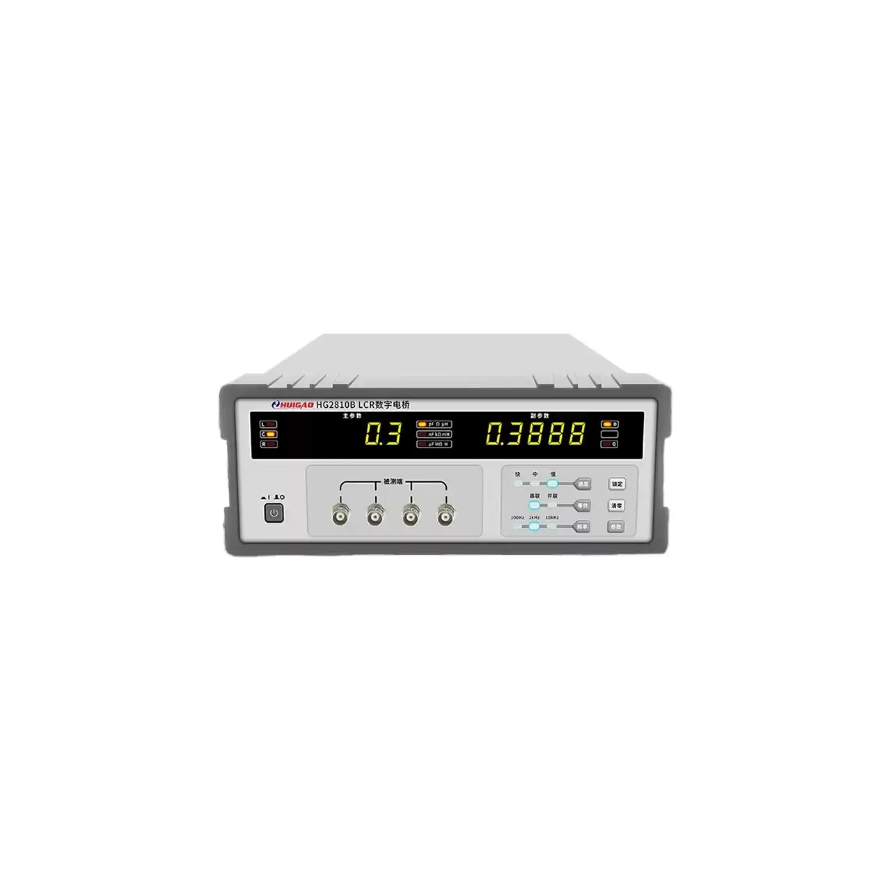
Three models share one chassis and one display, and differ only in how far the frequency reaches: 300 kHz, 500 kHz and 1 MHz, all starting at 20 Hz. Basic accuracy is 0.05% across the three, and the frequency is continuous with 1 mHz resolution rather than a list of fixed points.
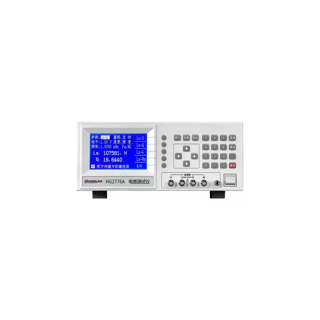
The front panel carries a 7-inch colour display, a column of soft keys beside it, a rotary knob and a numeric keypad at the right, and the coaxial test terminals along the lower edge. The case is 400 mm wide, 132 mm high and 6.8 kg, which is a bench instrument rather than a portable one. The rear panel carries the device, external trigger, handler, serial and barcode connectors.
How the LCR bridge works
The instrument applies a sine wave at the chosen frequency and level, and measures the voltage across the component and the current through it. Both signals are resolved into an in-phase and a quadrature component; their ratio gives impedance and their angle gives phase. From that pair the instrument derives whichever parameter set the operator has chosen, in series or in parallel form.
Four terminals separate the current path from the voltage sense path, so the impedance of the leads and of the contact does not enter the result. Because the residual of the fixture itself still matters at the edges of the range, the instrument provides open and short calibration at spot frequencies, a full-frequency zero and a load calibration.
The sweep functions use the same engine repeatedly. A list sweep steps through up to 40 programmed points of frequency, level or bias; a graphical sweep runs continuously across a range and plots the result. The internal bias supply, adjustable between −5 V and +5 V, shifts the operating point of the component during either.
How to select the right LCR bridge
The first question is the highest frequency the parts are specified at. A part quoted at 100 kHz is comfortably inside all three models; one quoted at 400 kHz needs HG7829B or HG7829C; one quoted at 1 MHz needs HG7829C. Buying beyond that costs money and buys nothing.
The second is the test level. Five millivolts to 2 V covers most small-signal work, and the enhanced version extends that to 10 V for parts that need a larger drive. The level has to be settable at the value the datasheet uses, because a ceramic capacitor measured at a different level will not match its quoted capacitance.
The third is bias. The internal supply covers a few volts either way, which is enough for the level dependence of a ceramic or an electrolytic; a part that operates at a high voltage needs an external bias fixture, and the instrument has to be specified with that in mind.
The fourth is how results leave the instrument: ten-bin sorting with counting for a line, a handler port for a fixture, USB or serial for logging, and GPIB where an older test system expects it. The fifth is throughput: 9 ms per reading is fast enough for a handler, and the averaging setting from 1 to 255 readings trades that speed for stability.
Measurement limitations and selection considerations
The instrument measures small-signal parameters. It does not apply a high voltage, so it cannot reproduce the bias conditions of a capacitor that works at several hundred volts, and it cannot test insulation or leakage.
The connection is part of the measurement. At 1 MHz, a few centimetres of lead is a significant impedance, and the fixture has to hold the part at a repeatable geometry. Calibration removes a fixed residual but not a residual that changes when the leads are moved, which is why a proper fixture matters more at the top of the frequency range than at the bottom.
Averaging and speed interact with the part, not only with the instrument. A high-value capacitor or a large inductor takes time to settle after the signal is applied, and a 9 ms reading taken before it has settled will be different from a 187 ms reading of the same part. Where the reading is used as a limit, the timing setting belongs in the test procedure.
Finally, the sweep functions describe a component, not a specification. A curve that looks smooth is reassuring, but a pass or fail decision still needs a limit, and the limit has to come from the drawing rather than from the shape of the plot.
Every value below is taken from source documentation. Where a parameter is not stated in the available material it is marked as information required rather than estimated.