- Test frequency
- Four, six or ten fixed points between 50 Hz and 100 kHz, by model
- Basic accuracy
- 0.2% on ZX8511DN; 0.1% on ZX8510BN, ZX8510BT and ZX8517BN; 0.05% or 0.1% on ZX8517BT depending on the table
- Test level
- 0.1 V, 0.3 V or 1 V rms on the three-level models; 0.1 V to 2 V on the wide-level models
- Impedance range
- 0.1 mΩ to 99.999 MΩ on the compact models; 0.01 mΩ to 99.9999 MΩ on the wide-level models
- Connection
- Four-wire Kelvin, with separate voltage sense and current drive pairs
- Measurement speed
- Up to 30 readings per second on ZX8510BT and ZX8517BT; 40 per second on ZX8511DN
- Sorting
- Four bins, BIN0 to BIN3, with pass, high and low lamps and a buzzer on the models that list it
- Interfaces
- RS232C, USB host and USB device on all; HANDLER on all but ZX8511DN
- Mains
- 100 to 120 V AC or 198 to 242 V AC, 46 to 64 Hz
- Body
- 216 × 87 × 275 mm or 310 × 110 × 315 mm
Most component drawings name one, two or three test frequencies, and a bench that can hit exactly those points does not need a continuous sweep. This group is built for that narrower job, and the differences between the five models are almost entirely about which points they can reach.
Product overview
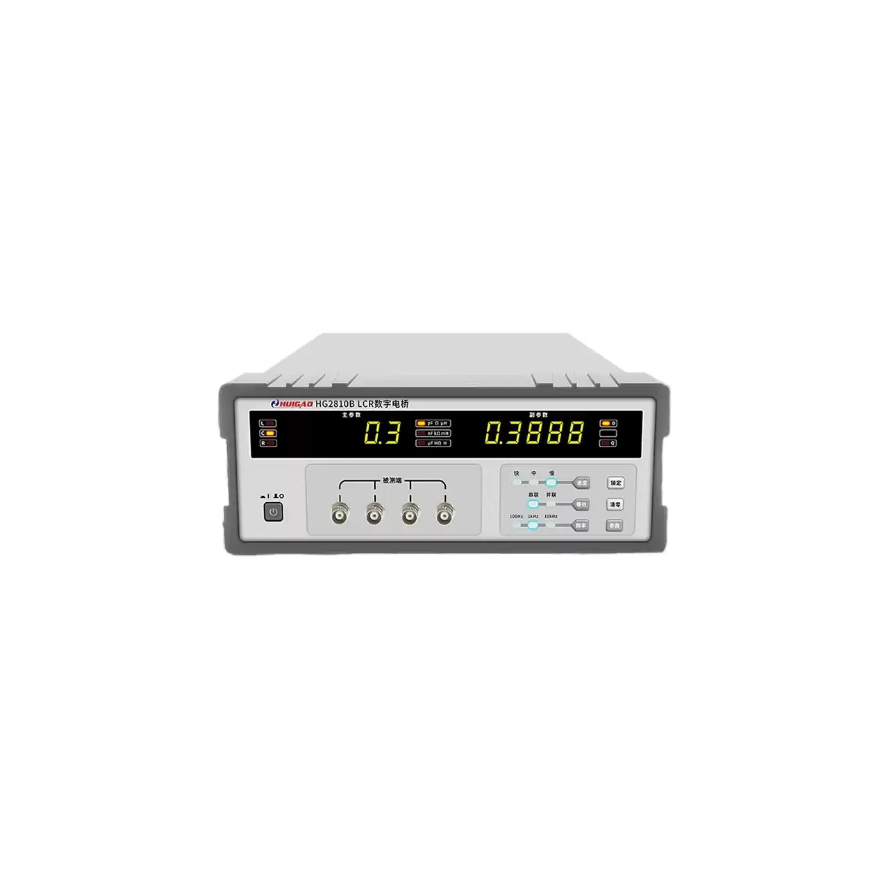
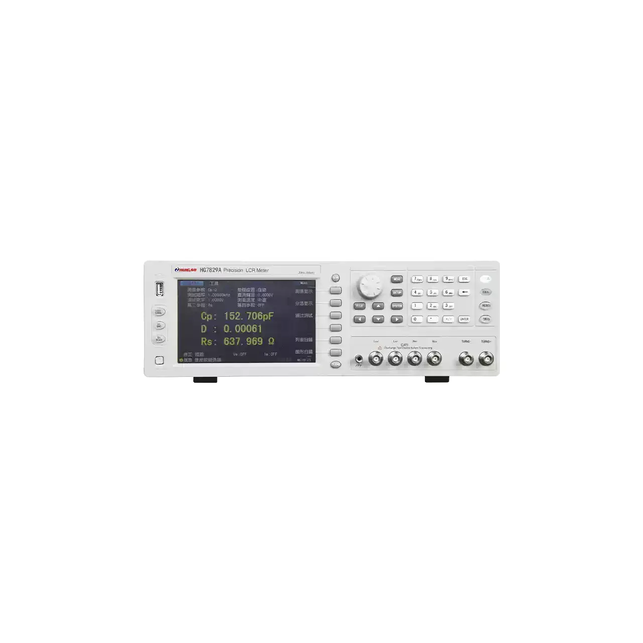
Five models sit in two body sizes. Three use a 216 mm case; two use a 310 mm case at 4.5 kg. All five use the same four-wire Kelvin terminals, the same colour display and the same sorting functions, and they differ in frequency points, test level and basic accuracy.
The smaller body carries the display at the left, soft keys beside it and the keypad at the right, with the four coaxial terminals along the lower edge. The larger body adds room for the wider-level signal source. Either one fits on a bench beside a fixture rather than on a rack.
How the LCR bridge works
The instrument applies a sine wave at one of its fixed frequencies and measures the voltage across the component and the current through it. Those two signals are separated into an in-phase and a quadrature part, which gives impedance and phase; from that pair the instrument derives inductance, capacitance, resistance and the loss terms.
The four-wire connection is what makes the result usable at low impedance. Two of the four leads carry the drive current and two sense the voltage at the component terminals, so the resistance of the leads and of the contact does not appear in the reading. Open and short calibration then removes what is left of the fixture itself.
Because the frequency set is fixed, the instrument is fast and simple: there is no sweep to configure, and a part is measured at a known point with a known level. The comparator turns that reading into a bin decision, and the lamps and buzzer report it at the fixture.
How to select the right LCR bridge
Start with the frequency points on the drawing. Four points to 10 kHz covers the common 100 Hz, 120 Hz, 1 kHz and 10 kHz calls. Ten points to 100 kHz adds 20 kHz, 40 kHz, 50 kHz and 100 kHz, which is where switching components and many film capacitors are specified. If a part is specified at a point that neither set includes, this group is the wrong choice and a continuous-frequency bridge is needed.
The second question is the test level. The three-level models offer 0.1 V, 0.3 V and 1 V; the wide-level models offer 10 mV to 2 V. A ceramic capacitor whose capacitance is quoted at a low level needs the second, and so does any part measured near its working level.
The third is bin count and interface. The models documented in detail sort into four bins and carry a HANDLER port, except for the ZX8511DN, which has no HANDLER and no bin table in the material. A line that grades parts needs the bin configuration confirmed before the order, not after; a bench that only accepts or rejects does not.
The fourth is physical size. The 216 mm models fit where a 310 mm case will not, and the difference matters when the instrument has to sit inside a test station rather than beside it.
Measurement limitations and selection considerations
The frequency set is fixed, so the instrument cannot show how a component behaves between the points it has. A capacitor whose value falls steadily with frequency will look acceptable at every available point and still be wrong at the frequency the circuit runs at, if that frequency is not one of them.
The basic accuracy figure is a headline. Accuracy varies with impedance and frequency, and the material refers to a separate accuracy table that is not included; where a reading is used as a limit, the accuracy at that specific impedance and frequency has to be established rather than assumed from the basic figure.
Contact and fixture dominate at the low end of the impedance range. A four-wire connection removes the lead resistance but not a poor contact at the component terminal, and a clip that sits on solder resist rather than on the pad will read high. The zeroing procedure has to be run with the fixture in the state it will be used in.
Finally, the reading is only comparable with another taken at the same frequency and level. Two models in this group with the same nominal accuracy will not agree if one is set to 1 V and the other to 0.1 V, which is why the test condition belongs in the procedure rather than in the operator’s memory.
Every value below is taken from source documentation. Where a parameter is not stated in the available material it is marked as information required rather than estimated.