Electrical Test & Measurement · LCR Meters

Winding Insulation Tester

Four impulse winding testers reaching up to 10 kV, with corona analysis, high-speed waveform capture, a 7-inch colour display and pass or fail outputs for inter-turn insulation testing of coils and windings.

HG9813 (4 models) ·

Key specifications

Pulse voltage
100 V to 3000 V on HG9813, 100 V to 5000 V on HG9815, 200 V to 6000 V on HG9816 and 300 V to 10,000 V on HG9810, all in 10 V steps at 5% ±10 V
Pulse energy
0.09 J on HG9813, 0.25 J on HG9815, 0.36 J on HG9816 and 0.5 J on HG9810
Inductance range
≥10 µH on HG9813, HG9815 and HG9816; ≥50 µH on HG9810
Test speed
15 per second on HG9813 and HG9815, 12 on HG9816 and 8 on HG9810
Waveform capture
Up to 100 MSa/s in 10 steps, 8-bit resolution, 6500-byte record depth and 1 to 32 sample averages
Display
7-inch 65k colour TFT, 800 × 480 dots, with a 650 × 256 waveform area and 1.5× magnification
Judgement methods
Area, area difference, corona discharge and phase difference
Storage
300 reference waveforms and settings inside the instrument, 600 on a USB drive, and statistics for up to 20,000 measurements
Interface
HANDLER, RS232C, USB Device and USB Host as standard, GPIB optional

Two coils can have the same inductance and the same resistance and still behave differently under a pulse, because one of them has a weakness between two turns that no steady-state measurement reaches. This range is built to make that difference visible.

Product overview

Four models share one measuring method and differ in how hard they can drive a winding. The pulse voltage runs from 3 kV to 10 kV across the range, the energy steps up with it, and the inductance floor rises at the top model because a larger pulse is intended for a larger winding.

Around that core sit the parts that make the instrument usable on a line: a colour display large enough to compare two traces, storage for reference waveforms, statistics on the results, and the interfaces a handler or a computer needs.

How the winding insulation tester works

The instrument discharges a pulse into the winding and records the voltage across it as the oscillation decays. The shape of that decay depends on the inductance of the winding, the capacitance between its turns and the losses in its insulation, so a change in any of them shows up as a change in the trace.

A known-good winding is measured first and its trace is stored. Each part afterwards is pulsed the same way and compared against that reference. A short between adjacent turns removes turns from the resonant network and shifts the response; a weakness that has not yet shorted may leave the low-frequency shape intact but add high-frequency activity.

Corona analysis looks for exactly that activity. A partial discharge emits a short burst of high-frequency energy, and the instrument’s sampling rate and corona display are there to catch it. Because the burst is brief, the capture has to be fast and the record has to be deep enough to hold the whole event.

Several pulses can be applied in one test, with demagnetising pulses at the end, so a winding is stressed more than once before a decision is made. That matters for faults that only appear after the insulation has been worked.

How to select the right winding insulation tester

Start with the test voltage. It comes from the insulation class of the winding and from the procedure the customer already uses, not from the highest number on the datasheet. A pulse above what the insulation can take will damage good parts, and the damage may only surface later.

Then check the inductance. Each model has a floor below which the response is too small to judge, and the high-voltage model has the highest floor because it is meant for large windings. A small coil on the largest instrument is the wrong pairing.

Then look at the energy and the speed. A large winding needs more energy to reach the test voltage, and a line that tests every part needs the faster model. The two move in opposite directions across the range, so the choice is a compromise that the production rate usually settles.

Then decide how the result is used. A bench uses the display and the foot switch; a line that sorts needs the handler lines; a line that records needs the serial or USB link. Send the winding drawing, the inductance and the insulation class, and a model, a lead and a fixture can be quoted against them.

Measurement limitations and selection considerations

The test judges a part against a reference, so the reference is part of the measurement. A trace stored from a marginal winding will pass marginal parts, and a reference taken at a different voltage or in a different fixture is a different test.

The pulse is a stress. A part that passes has survived that pulse at that energy; whether it survives the insulation test that follows, or the voltage in service, is a separate question, and a test that is too severe can create the fault it is meant to find.

Corona detection is sensitive to the environment as well as to the part. Humidity, surface contamination and the capacitance of the fixture all affect what the trace shows, so a comparison between shifts or between rooms has to be made under the same conditions. The material does not state the conditions behind the repeatability figure, which is why it should be established locally before a limit is set on it.

Finally, the method finds a difference, not a cause. A trace that departs from the reference tells the operator that this winding is not like the reference winding; whether the difference is a shorted turn, a damaged core or a handling fault has to be found by looking at the part.

Features

  • Corona acquisition with several corona modes and a dedicated corona display, which is aimed at insulation weaknesses that have not yet become a short
  • A sampling rate of up to 100 MSa/s with selectable averaging, so a fast discharge event can be captured rather than smoothed away
  • Four judgement methods on one instrument, allowing the same part to be judged by area, by phase or by corona activity depending on the fault being hunted
  • A 7-inch colour display with an enlarged waveform area, so the reference and the measured trace can be compared by eye before the instrument decides
  • Up to 32 test pulses and 8 demagnetising pulses per test, which allows a winding to be stressed repeatedly within one cycle
  • 300 reference sets inside the instrument and 600 on a USB drive, so a product changeover does not require the reference part to be found
  • Measurement statistics for up to 20,000 results, which turns the instrument into a record of a production run rather than a single reading
  • HANDLER, serial and both USB ports as standard, with GPIB as an option, so the instrument can be triggered and read by a line controller

Technical specifications

Every value below is taken from source documentation. Where a parameter is not stated in the available material it is marked as information required rather than estimated.
Pulse output
Pulse voltage, HG9813100 V to 3000 V, 10 V steps, tolerance 5% ±10 VStandard
Pulse voltage, HG9815100 V to 5000 V, 10 V steps, tolerance 5% ±10 VStandard
Pulse voltage, HG9816200 V to 6000 V, 10 V steps, tolerance 5% ±10 VStandard
Pulse voltage, HG9810300 V to 10,000 V, 10 V steps, tolerance 5% ±10 VStandard
Applied pulse countUp to 32 test pulses and up to 8 demagnetising pulsesStandard
Pulse energy, HG98130.09 J maximumStandard
Pulse energy, HG98150.25 J maximumStandard
Pulse energy, HG98160.36 J maximumStandard
Pulse energy, HG98100.5 J maximumStandard
Inductance range≥10 µH on HG9813, HG9815 and HG9816; ≥50 µH on HG9810Standard
Input impedance10 M, printed without a unit in the materialInformation required
Acquisition and judgement
Sampling rateUp to 100 MSa/s, selectable in 10 stepsStandard
Resolution8 bitsStandard
Record depth6500 bytesStandard
Sample averaging1 to 32Standard
Judgement methodsArea, area difference, corona discharge and phase differenceStandard
Corona analysisCorona acquisition with several corona modes and a corona displayStandard
Waveform measurementVoltage, frequency and time, read from the displayed waveformStandard
Trigger modesManual, including foot switch, external, internal and busStandard
Repeatability±1%, with the test conditions for that figure not statedStandard
Test speed, HG9813 and HG981515 per second maximumStandard
Test speed, HG981612 per second maximumStandard
Test speed, HG98108 per second maximumStandard
Judgement outputOK or NG on the display, LED indication and a buzzer alarmStandard
Display and storage
Screen7-inch 65k colour TFT, 800 × 480 dotsStandard
Waveform area650 × 256, with 1.5× magnificationStandard
Magnification wordingThe feature description states that magnification adds 50% to the display area, while the parameter table states 1.5×; both describe the same zoomStandard
Interface languageEnglish or Chinese, selectableStandard
Internal memory300 sets of reference waveform data and measurement settingsStandard
USB memory600 sets of reference waveform data and measurement settingsStandard
Measurement statisticsMeasurement time and result statistics, up to 20,000 recordsStandard
Interface
HANDLERSTART, STOP, PASS, FAIL, BUSY and EOC linesStandard
RS232CStandardStandard
USB DeviceUSB TMC and USB CDCStandard
USB HostFAT16 and FAT32, saving BMP, GIF and PNG images, CSV waveform and statistics files, and setting filesStandard
GPIBOptionalOptional
Rear panelDevice, HANDLER, RS232C and barcode connectors, mains inlet and fuseStandard
Power and environment
Mains supply220 V ±10%, 50 Hz ±5%Standard
Power consumption≤50 VAStandard
Operating temperature0 °C to 40 °CStandard
Operating humidity≤75% relative humidityStandard
Mechanical
Dimensions400 mm wide × 132 mm high × 350 mm deepStandard
Dimension orderOne table prints the same figures in the order height × width × depth (132 × 400 × 350); the values agreeStandard
Weight7.5 kgStandard
Test terminalsHV output and GNDStandard
Supplied accessoryHigh-voltage test lead, listed for all four modelsStandard
Full packing listNot stated in the materialInformation required

Available models

Selection table
Model Configuration Key ranges Availability
HG9813 100 V to 3000 V, 0.09 J, 15 tests per second Inductance ≥10 µH; the entry model in the range For small coils and low-voltage windings
HG9815 100 V to 5000 V, 0.25 J, 15 tests per second Inductance ≥10 µH The same inductance floor with a higher pulse voltage and energy
HG9816 200 V to 6000 V, 0.36 J, 12 tests per second Inductance ≥10 µH For windings that need a higher stress without the largest energy
HG9810 300 V to 10,000 V, 0.5 J, 8 tests per second Inductance ≥50 µH The high-voltage model, for larger windings and heavier insulation

Customization

  • GPIB interface as an option where the line already uses that bus
  • High-voltage test lead supplied with the instrument and available as a spare
  • Test fixtures for a particular stator, bobbin or transformer, since a wound part is contacted by a jig in volume testing
  • Foot switch for manual triggering at a bench

Certification and compliance

Certification documents not yet supplied

Certifications are only published once a certificate copy can be produced, so this section is deliberately empty rather than populated with assumed approvals. Tell us which approvals your application requires and we will confirm what is available for this instrument.

Parameters still to be confirmed

The following are required for a complete specification but are not stated in the documentation supplied to us. They are listed rather than estimated:

  • The test conditions behind the ±1% repeatability figure, which the material does not state
  • The unit of the input impedance, which the material prints only as 10 M
  • The individual corona modes offered by the corona acquisition function, which the material describes only in general terms
  • The complete packing list, of which only the high-voltage test lead is named
  • Whether a calibration certificate is supplied and to which standard
  • Warranty period and its terms
  • The function of the barcode connector on the rear panel, which is listed but not described
  • The resolution of the pulse voltage setting at the low end of each range, beyond the 10 V step
  • Whether the instrument is supplied with a foot switch or whether it is an accessory

Frequently asked questions

How do I choose between the four models?

By the pulse voltage the insulation has to withstand and by the size of the winding. The models step from 3 kV to 10 kV, and the two largest also differ in energy and in test speed. The 10 kV model needs a larger inductance before it can test, so a small coil is not better served by it.

What does corona analysis add?

A winding can pass an area comparison while still harbouring a partial discharge that will erode the insulation over time. Corona acquisition looks for the high-frequency burst that accompanies that discharge, and the dedicated display makes it visible. It is a way of finding a degradation that has not yet become a fault.

What has to be confirmed before a quotation?

The winding type, its inductance, the insulation class and the pulse voltage the procedure calls for, the number of test points and how the part is contacted, and how the instrument is triggered on the line. Those answers fix the model, the fixture and the interface.

Related products

Other models in the same range

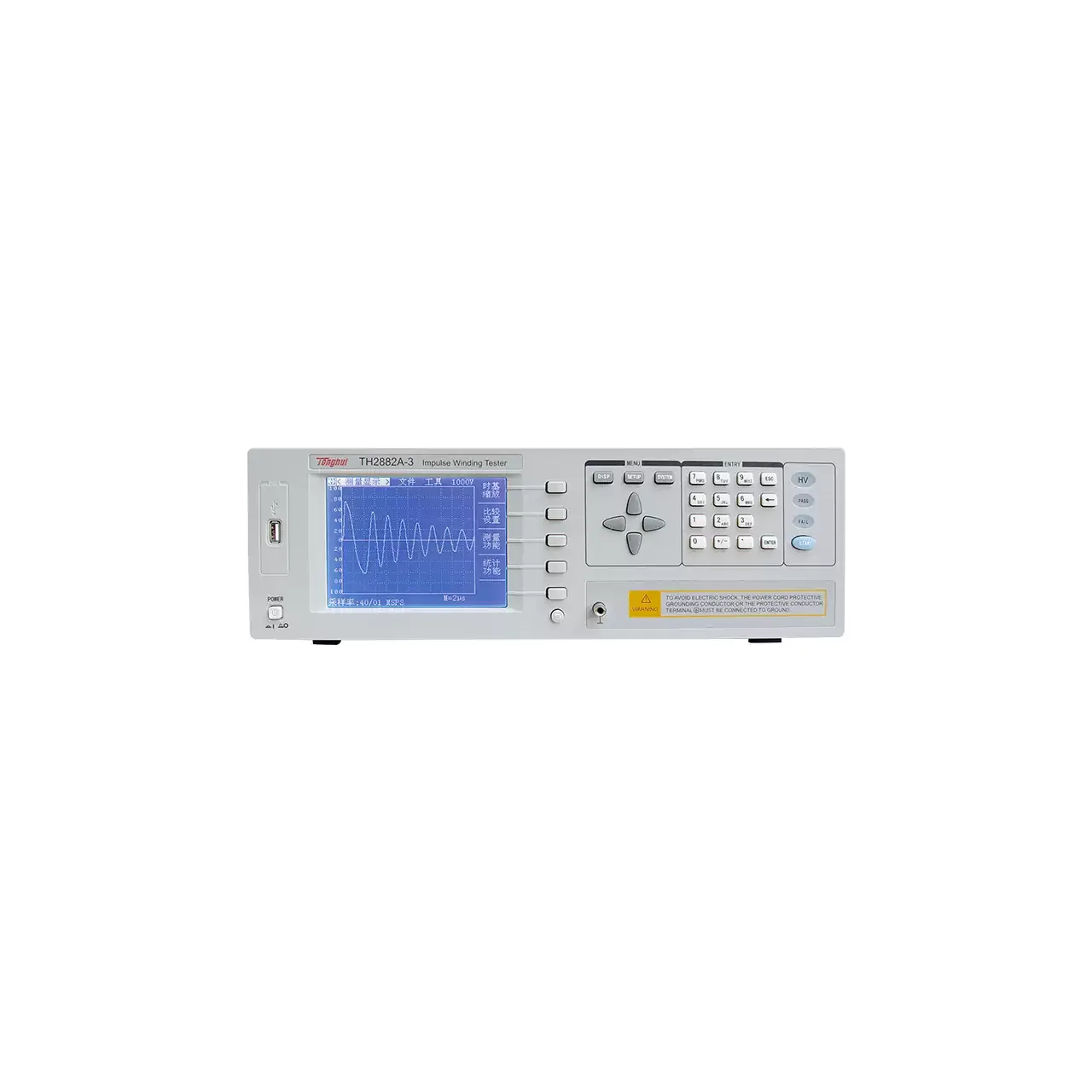
Bench impulse winding tester in a light grey case, with a colour LCD at the left showing a damped oscillatory waveform and two readings below it, a column of four soft keys beside the screen, a keypad and three status keys at the right, and a USB socket at the far left

TH2882A-3 (3 models) · LCR Meters

Impulse Winding Tester

Impulse winding testers that apply a high-voltage pulse to a coil and compare the response waveform against a reference, for finding inter-turn shorts, weak insulation and winding faults in single-phase and three-phase parts.

Output pulse voltage
300 V to 3000 V ±5% in 50 V steps on TH2882A-3; 500 V to 5000 V ±5% in 100 V steps on TH2882A-5; the model list gives the same 500 V to 5000 V for TH2882AS-5
Pulse energy
≤90 millijoules on TH2882A-3; ≤250 millijoules on TH2882A-5 and, in the model list, on TH2882AS-5
Inductance range
≥10 µH on TH2882A-3; ≥20 µH on TH2882A-5; ≥200 µH on TH2882AS-5
Waveform sampling
≤40 MSPS at 8 bit
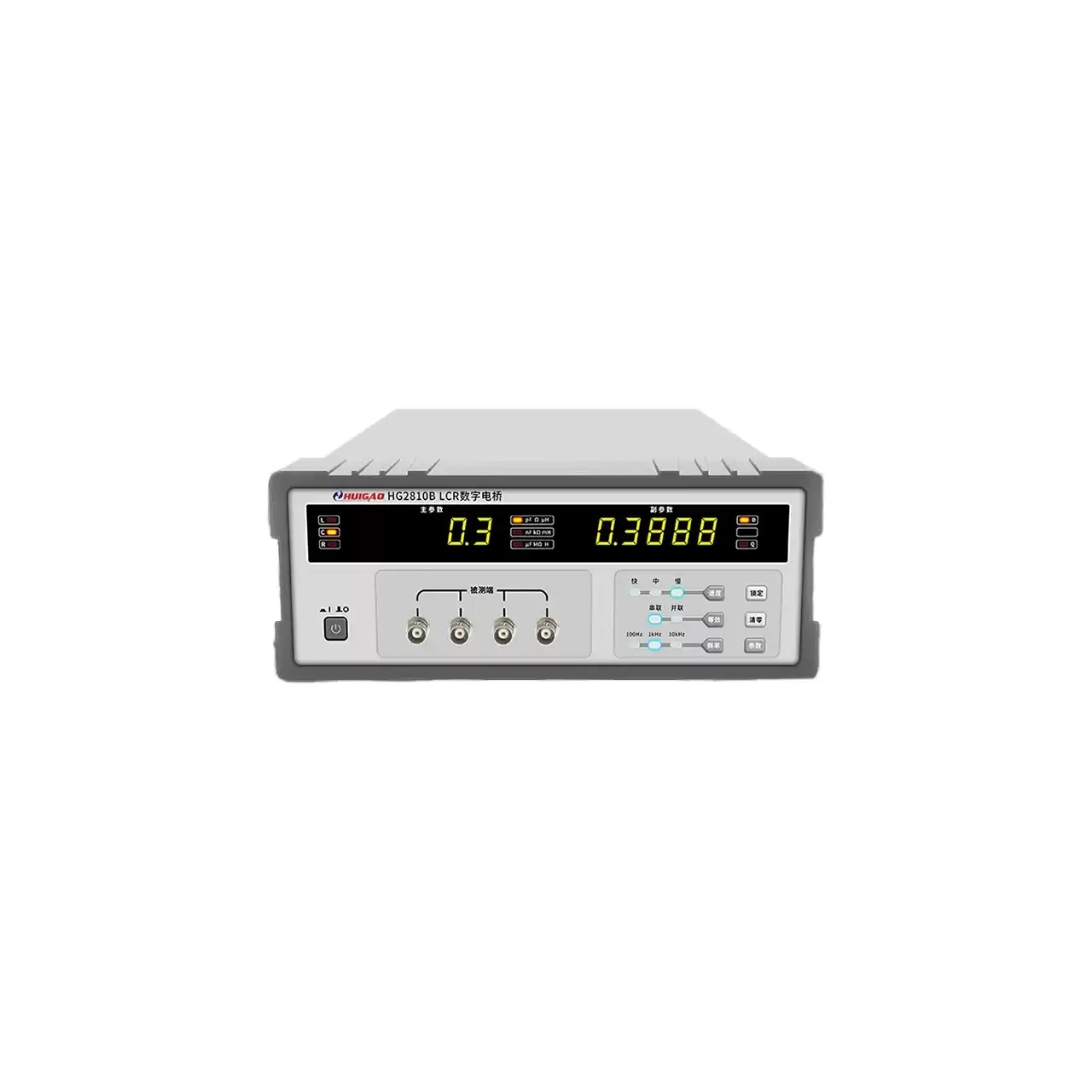
Bench LCR bridge in a grey case, with a five-digit LED display showing a primary and a secondary reading, four coaxial test terminals across the lower centre of the panel, a column of range and function keys at the right and the power switch at the left

HG2810B (6 models) · LCR Meters

Bench LCR Digital Bridge

Bench LCR bridges covering fixed-frequency and wide-band models, with 0.10% or 0.05% basic accuracy, five-terminal connections, bin sorting and optional RS232 and HANDLER interfaces for incoming inspection and production sorting.

Test frequencies
100 Hz, 120 Hz, 1 kHz and 10 kHz on the general models; up to 100 kHz on HG2817 and HG2817B; 8 points to 100 kHz on HG2817D; 37 points from 50 Hz to 200 kHz on HG2817A
Basic accuracy
0.10% on the general models; 0.05% on HG2816A and HG2817A
Test level
0.3 V on HG2810B; 0.1 V, 0.3 V or 1.0 V on most other models; 10 mV to 2.00 V in 10 mV steps on HG2816A and HG2817A
Display ranges
L 0.01 µH to 99999 H and C 0.01 pF to 99999 µF on the general models, with wider ranges on the LCD models

Request a quotation for the HG9813

Send the configuration you need and we will confirm availability, lead time and terms. Minimum order quantity is 1 pc.

Request for quotation

Request a quotation - HG9813

Send the technical detail and we will confirm availability, lead time and terms. In-stock items ship within 48 hours; customized specifications typically take 2-10 days. Minimum order quantity is 1 pc.

The more of this you can give us, the fewer exchanges are needed before we can quote.
No file chosen
Datasheet, drawing, BOM or photograph. One file, up to 10 MB (PDF, Office, image or ZIP).

By submitting this form you agree that we may contact you about this enquiry. We do not sell or share enquiry data. See our privacy policy.

Items held in stock are dispatched within 48 hours of order confirmation. Customized specifications are produced to order and typically ship within 2 to 10 days. Transit time then depends on the shipping method and destination.

Request a Quote WhatsApp