Electrical Test & Measurement · LCR Meters

Coil and Winding Turns Counter with DC Resistance

Bench turns counters for coils up to 80,000 turns, with automatic ranging, no calibration before a measurement, and DC resistance measurement on the two R models.

CH1201 (4 models) ·

Key specifications

Turns range
1 to 80,000 on CH1201 and CH1201R; 1 to 30,000 on CH1200 and CH1200R
Turns accuracy
±0 turns to ±1 turn at the low end, then ±0.2% or ±0.3%, and ±0.5% at the top of the 80,000 range
Turns speed
3 readings per second on CH1201; 1.5 on CH1200
DC resistance
100 µΩ to 200 kΩ on CH1201R; 100 µΩ to 20 kΩ on CH1200R
Resistance accuracy
0.2%, measured four-terminal
Coil size
Inside diameter above 4 mm, outside diameter below 120 mm, height below 110 mm
Sensors
Ø9.5, Ø6 and Ø4 mm, with Ø4 supplied as standard
Display
LED digital display
Interface
RS232C as standard
Body
335 × 320 × 290 mm, about 6 kg

Counting turns by hand is slow, and counting them by eye is unreliable above a few hundred. A turns counter replaces both with a number on a display, and the useful questions are how large a coil it can take, how fine the count is at the low end, and whether the same station can also check the winding resistance.

Product overview

Four models share one case and one sensing head. Two count to 80,000 turns at 3 readings per second; two count to 30,000 at 1.5. Within each pair, the model with an R suffix adds DC resistance measurement through a four-terminal connection.

The case is 335 mm wide, 320 mm deep and about 6 kg, with the sensing rod rising from the top cover and the display, alarm keys and power switch across the front. Three sensor diameters are available, and the smallest is supplied as standard.

How the turns counter works

The coil is placed over the sensing rod, which couples the winding to the instrument. The number of turns is derived from that coupling rather than counted mechanically, so the coil does not have to be rotated and the count appears as soon as the part is in position. The instrument selects its range automatically, which is why there is no range switch and no calibration step before a measurement.

The sensing diameter has to suit the bore of the coil. A head that is too small for a large coil couples weakly; the material recommends the largest head when the inside diameter is above 30 mm. The coil also has to fit within the stated envelope: inside diameter above 4 mm, outside diameter below 120 mm and height below 110 mm.

On the two R models, the same instrument measures the DC resistance of the winding through a four-terminal connection, with separate current and voltage leads so that the lead and contact resistance stay out of the reading. That is what makes a result in the hundreds of microhms meaningful, and it is also the check that catches a winding made with the wrong wire gauge.

How to select the right turns counter

The first question is the largest turn count the bench will see. Thirty thousand covers most small and medium transformers and relay coils; eighty thousand covers larger machine windings. Buying the larger range also buys the finer low-end accuracy, since the 80,000 models are specified at zero error below 300 turns.

The second is whether resistance has to be measured at the same station. If the winding resistance is already checked elsewhere, the plain models are enough. If the count and the resistance belong to one operation, the R models remove a handling step, and the difference between them is the resistance range: 20 kΩ on the 30,000 model, 200 kΩ on the 80,000 model.

The third is the physical size of the coil. The envelope is fixed at 120 mm outside diameter and 110 mm height, and no model extends it. A coil outside that envelope needs a different fixture, not a different model.

The fourth is throughput. Three readings per second against 1.5 is the difference between keeping up with a winding machine and checking a batch afterwards.

Measurement limitations and selection considerations

The instrument counts turns on air-core coils and on transformer and motor windings. It is not intended for coils with a magnetic core or a magnetic ring, and the material states that parts below 4 mm in diameter which are magnetic cannot be tested at all. A magnetic core changes the coupling the count depends on, so the number is not merely less accurate — it is not meaningful.

The count is a number, not a diagnosis. A coil with the right number of turns and a shorted turn will still count correctly, and a coil wound with the wrong wire will count correctly as well. Those faults need a pulse test or a resistance measurement, which is the reason the R models exist and the reason a turns counter is usually one station in a line rather than the whole inspection.

The sensing head is a mechanical interface as much as an electrical one. A coil that sits loosely on the rod, or one whose leads cross the sensing area, will not repeat. The fixture and the way the operator places the part belong to the measurement.

Finally, the resistance reading is a DC measurement at low current. It says nothing about the AC resistance or the losses of the winding at the frequency it will actually run at, so a coil that passes the resistance check can still run hot.

Features

  • Two turn ranges, 30,000 and 80,000, so a small transformer and a large generator winding can both be counted on the same bench
  • Segmented accuracy down to zero error below 300 turns on the 80,000 model, which is where a hand-wound small coil is usually checked
  • Automatic ranging with no calibration before a measurement, so an operator places the coil and reads the number
  • Resistance measurement on the two R models through a four-terminal connection, which removes lead resistance from a reading in the hundreds of microhms
  • Three sensor diameters, so the sensing head can be matched to the bore of the coil rather than the coil to the head
  • A buzzer that can be set to report an open winding, so a broken coil is caught at the same station as a wrong count
  • 3 readings per second on the 80,000 model, fast enough to keep pace with a winding machine
  • RS232C fitted as standard across the range

Technical specifications

Every value below is taken from source documentation. Where a parameter is not stated in the available material it is marked as information required rather than estimated.
Turns measurement
Range, CH1201 and CH1201R1 to 80,000 turnsStandard
Range, CH1200 and CH1200R1 to 30,000 turnsStandard
Accuracy, CH1201 and CH1201R1 to 300 turns ±0 turns; 300 to 500 turns ±1 turn; 500 to 20,000 turns ±0.2%; 20,000 to 80,000 turns ±0.5%Standard
Accuracy, CH1200 and CH1200R1 to 500 turns ±1 turn; 500 to 30,000 turns ±0.3%Standard
Accuracy, selection tableAll four models printed as ±0.5%, which the segmented table contradictsInformation required
Speed, CH1201 and CH1201R3 readings per secondStandard
Speed, CH1200 and CH1200R1.5 readings per secondStandard
RangingAutomatic, with no range change by the operatorStandard
Calibration before useNot requiredStandard
Resistance measurement
Fitted toCH1201R and CH1200R onlyStandard
Range, CH1201R100 µΩ to 200 kΩStandard
Range, CH1200R100 µΩ to 20 kΩStandard
Accuracy0.2%Standard
Speed, CH1201R5 readings per secondStandard
Speed, CH1200R3 readings per secondStandard
ConnectionFour-terminal, with separate voltage sense and current drive pairsStandard
Coil and sensor
Inside diameterAbove 4 mmStandard
Outside diameterBelow 120 mmStandard
HeightBelow 110 mmStandard
Sensor sizesØ9.5 mm, Ø6 mm and Ø4 mmStandard
Sensor suppliedØ4 mm as standard; Ø6 and Ø9.5 as optionsStandard
Sensor choiceØ9.5 mm is recommended when the coil inside diameter is above 30 mmStandard
Magnetic partsCoils with a magnetic core or a magnetic ring are outside what the instrument can testStandard
AlarmBuzzer selectable for open-circuit and phase indicationStandard
Interface, power and mechanical
InterfaceRS232C, 9-pin, as standardStandard
Interface purposeDescribed once as remote control and data collection with SCPI, and once as factory calibration onlyInformation required
Mains supply198 to 242 V AC, 47.5 to 52.5 HzStandard
Power consumption30 VA or belowStandard
Operating temperature0 °C to 40 °CStandard
Operating humidity90% RH or belowStandard
Dimensions335 mm × 320 mm × 290 mm, width by height by depthStandard
WeightAbout 6 kgStandard
Optional accessoryA coil test clip for the two R modelsOptional
Supplied with the instrumentMains lead, test lead, certificate and manualStandard

Available models

Selection table
Model Configuration Key ranges Availability
CH1201 Turns only, 335 × 320 × 290 mm, about 6 kg 1 to 80,000 turns; 3 readings per second; no resistance function The widest turn range
CH1201R Turns and resistance, 335 × 320 × 290 mm, about 6 kg 1 to 80,000 turns; resistance 100 µΩ to 200 kΩ at 5 readings per second Adds the wider resistance range
CH1200 Turns only, 335 × 320 × 290 mm, about 6 kg 1 to 30,000 turns; 1.5 readings per second; no resistance function The shorter turn range
CH1200R Turns and resistance, 335 × 320 × 290 mm, about 6 kg 1 to 30,000 turns; resistance 100 µΩ to 20 kΩ at 3 readings per second The shorter range with resistance

Customization

  • A coil test clip for a particular former or terminal arrangement
  • Sensor heads in the three available diameters
  • Cabling to a computer or a winding machine through the serial port

Certification and compliance

Certification documents not yet supplied

Certifications are only published once a certificate copy can be produced, so this section is deliberately empty rather than populated with assumed approvals. Tell us which approvals your application requires and we will confirm what is available for this instrument.

Parameters still to be confirmed

The following are required for a complete specification but are not stated in the documentation supplied to us. They are listed rather than estimated:

  • The correct turns accuracy, printed as ±0.5% for all four models in the selection table and as a segmented specification in the parameter table
  • The correct purpose of the RS232C port, described once as remote control and data collection with SCPI and once as factory calibration only
  • The meaning of the alarm setting described as open-circuit and phase, which the material does not explain further
  • The maximum wire diameter or coil weight the sensing head can accept, which the material does not state
  • The measurement principle and the excitation used by the sensing head, which the material does not describe
  • Whether the selection table rows for speed and accuracy are transposed, since their values appear in the opposite order to the parameter table
  • Calibration certificate availability and interval
  • Warranty period and its terms
  • Whether the coil test clip is supplied or only optional

Frequently asked questions

Does the counter work on a coil with a magnetic core?

No. The material states that the instrument is intended for air-core coils, transformers and similar wound components, and that coils with a magnetic ring or a magnetic core are outside its range. A magnetic core changes the coupling between the winding and the sensor and the count cannot be trusted. The same restriction applies to any part below 4 mm in diameter that is magnetic.

What decides between the 30,000 and the 80,000 turn model?

The largest coil the bench will see, with margin. The 80,000 model also has the finer accuracy at the low end, with no error below 300 turns, which matters for small hand-wound coils. The 30,000 model counts at 1.5 readings per second against 3 on the 80,000 model, so a bench that counts many small coils is also better served by the larger model.

What has to be confirmed before a quotation?

The turn count and the physical size of the coil — inside diameter, outside diameter and height — whether a resistance reading is needed as well, the wire gauge and expected resistance, and whether the coil has a magnetic core. Those answers decide the model, the sensor diameter and whether a test clip is needed.

Related products

Other models in the same range

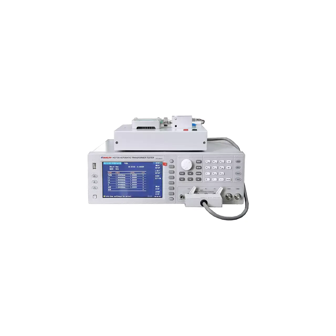
Bench transformer tester in a light grey case, with a colour LCD at the left listing turns ratio, inductance, leakage inductance and resistance readings, a column of soft keys and a numeric keypad at the right, and a test fixture resting on top of the case connected to the front panel by a ribbon cable and two coaxial leads

HG7729 (4 models) · LCR Meters

Transformer Comprehensive Tester

Four transformer testers with 20-channel scanning, LCR and DC resistance measurement at 0.05% basic accuracy, built-in DC bias and test frequencies from 20 Hz to 1 MHz for production testing of wound components.

Test frequency
20 Hz to 200 kHz on HG7729; 20 Hz to 300 kHz on HG7729A and HG7729B; 20 Hz to 1 MHz on HG7729C
Scanning
20-channel transformer scan on all four models
LCR parameters
|Z|, |Y|, C, L, X, B, R, G, D, Q and phase, plus DC resistance, turns and phase
Transformer scan parameters
Turns ratio, number of turns, phase, inductance, capacitance, leakage inductance, quality factor, AC resistance, DC resistance, balance, pin short and LED
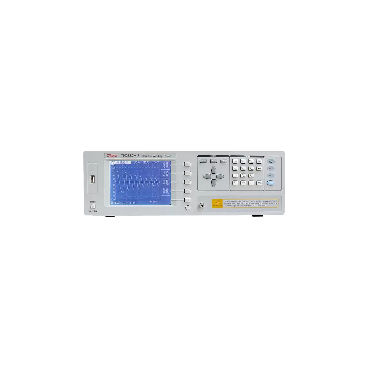
Bench impulse winding tester in a light grey case, with a colour LCD at the left showing a damped oscillatory waveform and two readings below it, a column of four soft keys beside the screen, a keypad and three status keys at the right, and a USB socket at the far left

TH2882A-3 (3 models) · LCR Meters

Impulse Winding Tester

Impulse winding testers that apply a high-voltage pulse to a coil and compare the response waveform against a reference, for finding inter-turn shorts, weak insulation and winding faults in single-phase and three-phase parts.

Output pulse voltage
300 V to 3000 V ±5% in 50 V steps on TH2882A-3; 500 V to 5000 V ±5% in 100 V steps on TH2882A-5; the model list gives the same 500 V to 5000 V for TH2882AS-5
Pulse energy
≤90 millijoules on TH2882A-3; ≤250 millijoules on TH2882A-5 and, in the model list, on TH2882AS-5
Inductance range
≥10 µH on TH2882A-3; ≥20 µH on TH2882A-5; ≥200 µH on TH2882AS-5
Waveform sampling
≤40 MSPS at 8 bit

Request a quotation for the CH1201

Send the configuration you need and we will confirm availability, lead time and terms. Minimum order quantity is 1 pc.

Request for quotation

Request a quotation - CH1201

Send the technical detail and we will confirm availability, lead time and terms. In-stock items ship within 48 hours; customized specifications typically take 2-10 days. Minimum order quantity is 1 pc.

The more of this you can give us, the fewer exchanges are needed before we can quote.
No file chosen
Datasheet, drawing, BOM or photograph. One file, up to 10 MB (PDF, Office, image or ZIP).

By submitting this form you agree that we may contact you about this enquiry. We do not sell or share enquiry data. See our privacy policy.

Items held in stock are dispatched within 48 hours of order confirmation. Customized specifications are produced to order and typically ship within 2 to 10 days. Transit time then depends on the shipping method and destination.

Request a Quote WhatsApp