Electrical Test & Measurement · LCR Meters

Electrolytic Capacitor Leakage Current Tester

Bench leakage current tester for aluminium electrolytic capacitors, with a 0 to 500 V adjustable charging voltage, three current ranges from 0.01 µA to 30 mA and settable charge and discharge times.

HG2611D ·

Key specifications

Test voltage
0 to 500 V, continuously adjustable
Leakage ranges
0.01 to 3 µA, 3 µA to 3 mA, 3 mA to 30 mA
Reading error
±1% ±2 digits
Charge time
0 to 99 s, ±2%
Discharge time
0 to 9 s, ±2%
Maximum charging current
At least 200 mA
Maximum test current
At least 30 mA
Terminals
Two-terminal, shielded, with an outer shield ground
Mains
220 V ±10%, 50 or 60 Hz ±5%
Body
330 × 320 × 120 mm, about 5 kg

A leaking electrolytic capacitor rarely fails outright. It drifts, heats, and dries out over a service life that is shorter than the one on the datasheet, and the only warning is a leakage current that has climbed past its limit. Measuring that current is simple in principle and awkward in practice, because it is a microamp sitting on top of a charging current many thousand times larger.

Product overview

This is a single-model bench instrument for that measurement. It supplies an adjustable direct voltage up to 500 V, holds the capacitor at that voltage for a set time, measures the residual current and then discharges the part before the fixture is opened.

The front panel carries a digital display, the voltage and time settings, and the two shielded test terminals. The case is 330 mm wide at about 5 kg, and a high-voltage warning is fitted to the body. The instrument is supplied with a mains lead and a test fixture for the capacitor package.

How the leakage tester works

The instrument charges the capacitor through a current-limited source until the terminal voltage reaches the set value, then holds that voltage while the current falls. What is displayed after the hold is the leakage current: the small conduction through the dielectric and the seal that continues once the plates are fully charged.

The hold time is the part of the procedure that decides the reading. A capacitor that has just been charged is still absorbing, and its current is falling steeply; the same capacitor a minute later sits on a much flatter curve. Setting the charge time between 0 and 99 s fixes a point on that curve, so that two capacitors, or two production lots, are compared at the same place. The discharge time, up to 9 s, is set for the same reason — to bring the part down predictably before it is handled.

Three current ranges cover 0.01 µA to 30 mA, and the reading error is ±1% ±2 digits. The over-limit indication, at ±3%, is what turns the reading into a pass or fail without the operator comparing numbers.

How to select the right leakage tester

There is one model here, so selection is about matching the procedure rather than choosing between variants. The first question is the test voltage: it has to reach the rated voltage of the parts, and 500 V covers the common 400 V and 450 V power-supply cans as well as low-voltage parts.

The second is capacitance, because it sets the charging time. A small part reaches its test voltage in a second; a large can draws the full charging current for much longer, and if the charge time is shorter than the time needed to reach the voltage, the instrument is still measuring charging current when the reading is taken.

The third is the leakage limit itself. A limit in the low microamps needs the lowest range and a stable fixture; a limit in the milliamps is easier to measure but more likely to be affected by the part heating during the test. The fourth is the fixture: terminal spacing, can diameter and whether the part is tested before or after the seal is fitted decide the jig more than the instrument does.

Send the capacitance, the rated voltage, the leakage limit and the hold time in the procedure, and the fixture can be specified with the instrument.

Measurement limitations and selection considerations

The measurement is made at direct voltage, so it describes the dielectric under a steady field and not the behaviour of the capacitor in a circuit. Equivalent series resistance, capacitance tolerance and impedance at frequency are separate measurements, and a capacitor that passes a leakage test can still be a poor part for a switching supply.

Temperature is the dominant influence on leakage current. A part measured cold and a part measured warm will not agree, and the difference can be larger than the tolerance band. Testing at a controlled ambient, or at least at a consistent one, matters more than the instrument’s own accuracy figure.

The hold time also has to be long enough for the reading to be meaningful on a large can, which is the practical reason the charge timer goes to 99 s. Where the procedure calls for a longer soak than that, the instrument has to be used with an external timing step rather than stretched beyond its setting.

Finally, the reading includes the leakage of the fixture and of the surface between the terminals. A dirty fixture at 500 V can leak more than the capacitor being tested, which is why the terminals are shielded and why a zero check with no part fitted belongs in the procedure.

Features

  • Charging voltage adjustable from 0 to 500 V, so a capacitor rated at 450 V and one rated at 25 V are tested at their own working voltage rather than at a fixed one
  • Charge time settable up to 99 s, which is what a large can needs before its leakage current stops falling
  • Discharge time settable up to 9 s, so the capacitor is brought down in a controlled way before the fixture is opened
  • Three current ranges spanning 0.01 µA to 30 mA, covering a small signal capacitor and a large power-supply can on one instrument
  • A charging current of at least 200 mA, which shortens the wait on a high-capacitance part
  • Over-limit indication at ±3%, so a capacitor that fails the limit is flagged rather than left to the operator to judge
  • Two-terminal shielded connection with an outer shield ground, which keeps stray pickup out of a measurement made at microamp level

Technical specifications

Every value below is taken from source documentation. Where a parameter is not stated in the available material it is marked as information required rather than estimated.
Measurement
Measured parameterLeakage currentStandard
Test voltage0 to 500 V, continuously adjustableStandard
Leakage current ranges0.01 to 3 µA, 3 µA to 3 mA, 3 mA to 30 mAStandard
Reading error±1% ±2 digitsStandard
Maximum test currentAt least 30 mAStandard
Maximum charging currentAt least 200 mAStandard
Leakage range, second readingPrinted in one place as 0.01 µA to 3 A, which the three-range table contradictsInformation required
DisplayDigitalStandard
Timing
Charge time0 to 99 s, accuracy ±2%Standard
Discharge time0 to 9 s, accuracy ±2%Standard
Over-limit indication error±3%Standard
SequenceCharge, hold and measure, then dischargeStandard
Connection and electrical
Test terminalsTwo-terminal, shielded, with an outer shield groundStandard
Mains supply220 V ±10%, 50 or 60 Hz ±5%Standard
Operating temperature0 °C to 40 °CStandard
Operating humidityBelow 90% RHStandard
High-voltage markingA high-voltage warning is fitted to the bodyStandard
Mechanical
Dimensions330 mm × 320 mm × 120 mm, width by height by depthStandard
WeightAbout 5 kgStandard
Supplied with the instrumentMains lead and a test fixture for this modelStandard
Kelvin lead listed in the materialListed as compatible with this model, although the instrument measures leakage current through a two-terminal connectionInformation required

Available models

Selection table
Model Configuration Key ranges Availability
HG2611D Leakage current tester with settable charge and discharge times 0 to 500 V; 0.01 µA to 30 mA in three ranges; charge 0 to 99 s, discharge 0 to 9 s The only leakage tester in the material

Customization

  • Test fixtures for a particular can size or terminal spacing
  • Test leads suited to the fixture in use

Certification and compliance

Certification documents not yet supplied

Certifications are only published once a certificate copy can be produced, so this section is deliberately empty rather than populated with assumed approvals. Tell us which approvals your application requires and we will confirm what is available for this instrument.

Parameters still to be confirmed

The following are required for a complete specification but are not stated in the documentation supplied to us. They are listed rather than estimated:

  • The correct leakage current range, printed once as 0.01 µA to 3 A and once as three ranges from 0.01 µA to 30 mA
  • The voltage at which each leakage range is specified, and the resolution on the lowest range
  • The test voltage accuracy and its stability over the 0 to 500 V span
  • Whether the over-limit indication is a relay output, a front-panel lamp or both
  • The insulation and safety rating of the test fixture at 500 V
  • The model and terminal spacing of the supplied test fixture
  • Whether the Kelvin low-resistance lead listed in the accessory table is actually supplied for this model, since the instrument uses a two-terminal connection
  • Calibration certificate availability and standard
  • Warranty period and its terms

Frequently asked questions

Why does the test need a settable charge time rather than a fixed one?

Because leakage current in an electrolytic capacitor falls slowly after the voltage is applied, and the value that matters is the one reached once the dielectric has settled. A small part settles in a few seconds; a large can may take tens of seconds. A fixed short charge time would read the tail of the charging current as if it were leakage and reject good parts. The 0 to 99 s setting lets the hold time match the part, and it has to be written into the test procedure so that every unit is compared at the same point in the curve.

What is the difference between the maximum charging current and the maximum test current?

The charging current is what the instrument can deliver while bringing the capacitor up to the test voltage, and it sets how long the charge phase takes; the test current is the upper limit of the current it can measure while holding. A large capacitance needs a large charging current to reach the voltage in reasonable time, while the leakage being measured afterwards is many orders of magnitude smaller.

What has to be confirmed before a quotation?

The capacitance and voltage rating of the parts, the leakage limit and the test voltage at which that limit is specified, the hold time the procedure calls for, and how the capacitors will be contacted in the fixture. Those answers fix the range, the timing settings and the fixture.

Related products

Other models in the same range

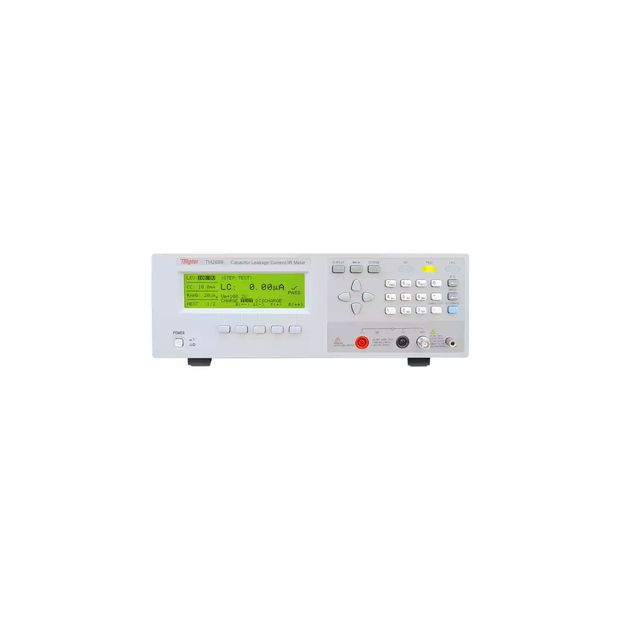
Bench capacitor leakage tester in a light grey case, with a backlit dot matrix display at the left showing a leakage current reading and charge status, function keys and a numeric keypad at the right, and a red high-voltage terminal beside two measurement terminals at the lower right

TH2689 (4 models) · LCR Meters

Capacitor Leakage Current Tester

Bench capacitor leakage testers with adjustable test voltage, leakage current measurement down to the nanoamp region, insulation resistance to 99.99 GΩ, timed charging and comparator limits.

Test voltage
1 V to 800 V on TH2689; 1 V to 500 V on TH2689A; 0 to 200 V and 0 to 500 V on TH2686N and TH2686C
Voltage accuracy
±(0.5% of setting + 0.2 V) on TH2689 and TH2689A; ±1% of setting + 1 digit on TH2686N
Leakage current range
0.001 µA to 20.00 mA on TH2689 and TH2689A; 10 nA to 19.99 mA with 1 nA resolution on TH2686N; 0 to 30 mA in 10 ranges on TH2686C
Insulation resistance
0.01 MΩ to 99.99 GΩ on TH2689 and TH2689A
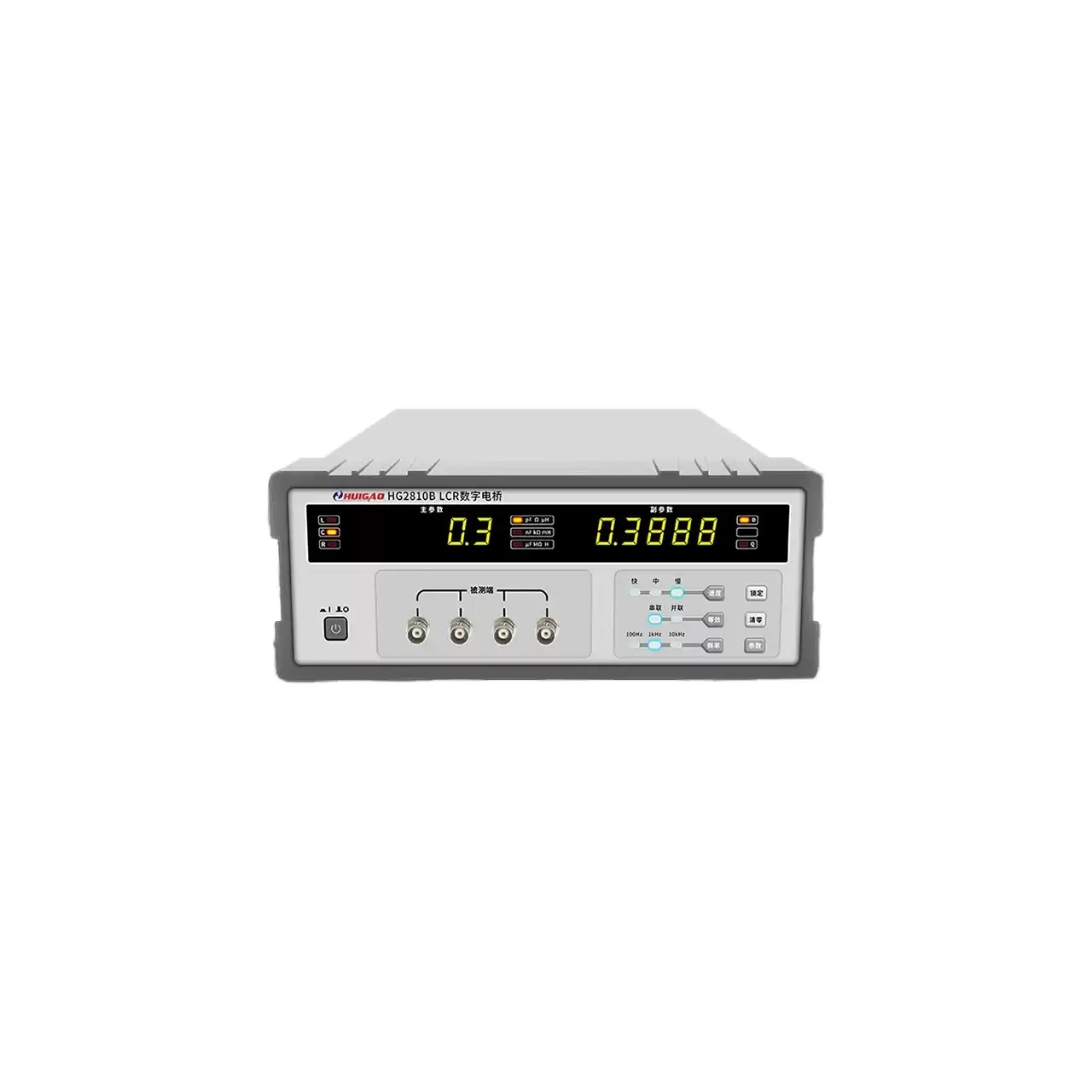
Bench LCR bridge in a grey case, with a five-digit LED display showing a primary and a secondary reading, four coaxial test terminals across the lower centre of the panel, a column of range and function keys at the right and the power switch at the left

HG2810B (6 models) · LCR Meters

Bench LCR Digital Bridge

Bench LCR bridges covering fixed-frequency and wide-band models, with 0.10% or 0.05% basic accuracy, five-terminal connections, bin sorting and optional RS232 and HANDLER interfaces for incoming inspection and production sorting.

Test frequencies
100 Hz, 120 Hz, 1 kHz and 10 kHz on the general models; up to 100 kHz on HG2817 and HG2817B; 8 points to 100 kHz on HG2817D; 37 points from 50 Hz to 200 kHz on HG2817A
Basic accuracy
0.10% on the general models; 0.05% on HG2816A and HG2817A
Test level
0.3 V on HG2810B; 0.1 V, 0.3 V or 1.0 V on most other models; 10 mV to 2.00 V in 10 mV steps on HG2816A and HG2817A
Display ranges
L 0.01 µH to 99999 H and C 0.01 pF to 99999 µF on the general models, with wider ranges on the LCD models

Request a quotation for the HG2611D

Send the configuration you need and we will confirm availability, lead time and terms. Minimum order quantity is 1 pc.

Request for quotation

Request a quotation - HG2611D

Send the technical detail and we will confirm availability, lead time and terms. In-stock items ship within 48 hours; customized specifications typically take 2-10 days. Minimum order quantity is 1 pc.

The more of this you can give us, the fewer exchanges are needed before we can quote.
No file chosen
Datasheet, drawing, BOM or photograph. One file, up to 10 MB (PDF, Office, image or ZIP).

By submitting this form you agree that we may contact you about this enquiry. We do not sell or share enquiry data. See our privacy policy.

Items held in stock are dispatched within 48 hours of order confirmation. Customized specifications are produced to order and typically ship within 2 to 10 days. Transit time then depends on the shipping method and destination.

Request a Quote WhatsApp