- Channels
- Two, four or eight depending on model
- AC output
- 0.05 to 5.00 kV, ±2%
- DC output
- 0.05 to 6.00 kV, ±2%, not fitted to AC-only models
- Leakage current
- AC 0 to 10.00 mA; DC 0 to 10.00 mA on the four-channel model
- Insulation resistance
- 0.1 to 50 GΩ, or 0.1 to 10 GΩ on the eight-channel models
- Resistance accuracy
- ±10% to 999 MΩ, ±20% to 10 GΩ, 25% of reading from 10 to 50 GΩ
- Arc detection
- Nine levels, default 5, from 20 mA down to 2.8 mA
- Memory
- 120 groups of 100 steps, or 64 files of 100 items in the feature text
- Display
- 4.3 inch TFT-LCD colour screen
- Body
- 310 × 110 × 415 mm and 15.5 kg on the single-channel family; 310 × 110 × 315 mm for the multi-channel group
A multi-point insulation test is only as repeatable as the switching between its points. Once the leads stop moving, the result depends on the instrument’s channel handling and on the sequence it runs, and those are the two things worth comparing.
Product overview
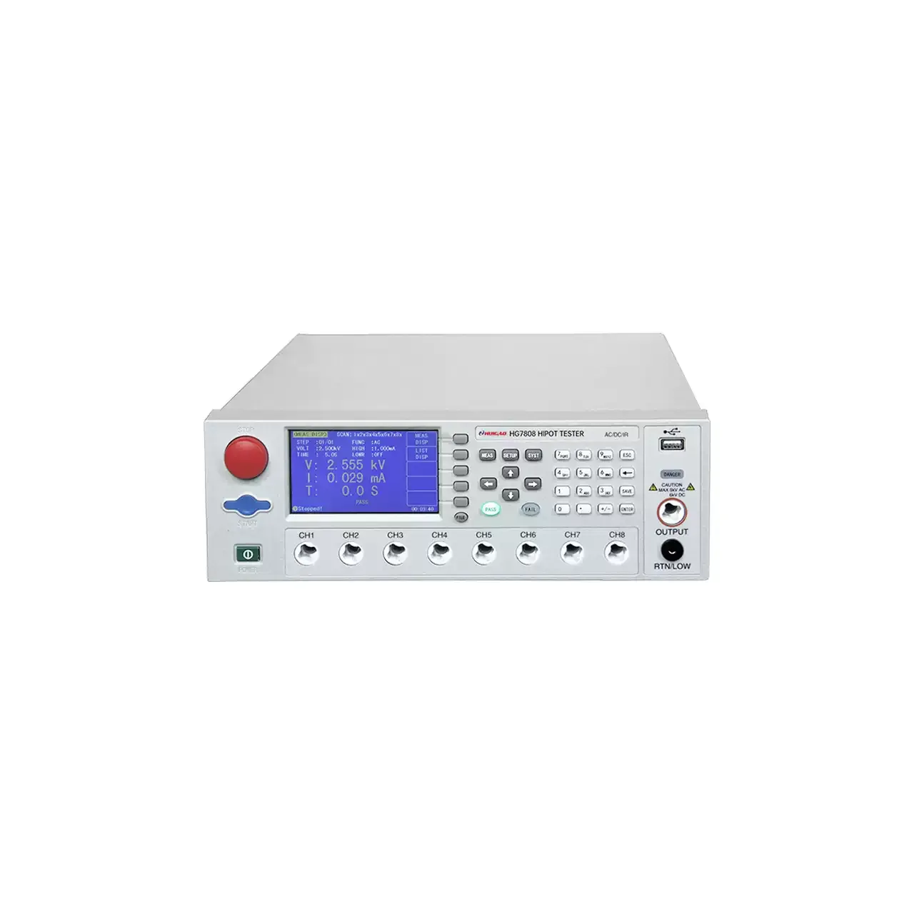
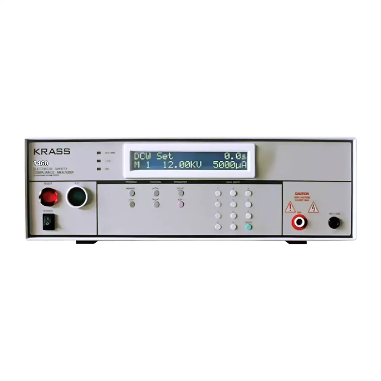
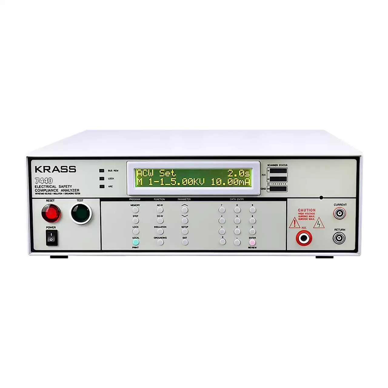
The range is built around a common test engine in bodies of different widths, with two, four or eight scanning channels. One family carries the alternating output only; the others add a direct output and an insulation resistance measurement. The channel count and the resistance range are the two figures that separate the models.
Channels are switched inside the instrument rather than by moving leads, so a fixture is wired once and the sequence steps through it. Stored files hold a complete test sequence, and those files can be copied to a USB drive and carried to another instrument of the same kind.
How the multi-channel tester works
The high voltage is raised over a programmed rise time, held for the test time and brought down over a fall time, and the current is compared with an upper and a lower limit throughout the hold. The upper limit is the breakdown criterion; the lower limit catches an item that is not connected, and it can be switched off for an item whose leakage is genuinely below the threshold.
In multi-channel mode the instrument switches the high voltage from one channel to the next and runs the stored step against each in turn. The original output terminals stay live and can act as a common return, which is what allows a fixture with one shared chassis point to be wired without switching the return as well.
Arc detection runs alongside the current comparison rather than replacing it. It responds to a fast change superimposed on the test current, which an ordinary current measurement averages away, and the nine levels correspond to progressively lower current thresholds.
Insulation resistance is measured at a lower direct voltage, and the accuracy is quoted in three bands because the current being measured falls into the nanoamp region at the top of the range. That is why the tolerance widens with resistance rather than staying constant.
How to select the right channel count
Count the points first, then decide whether the fixture will grow. Two channels cover a transformer with a primary and a secondary; four cover a three-phase item with a chassis point; eight cover a harness or a multi-winding component. The control, the memory and the sequence language are the same across the range, so the channel count is a fixture decision rather than a user-interface one.
The second question is whether a direct test and an insulation measurement are needed. One family carries the alternating output only, and the difference cannot be added later, so a product standard that calls for a direct test or a resistance reading decides the family before the channel count is considered.
The third is the resistance range. The eight-channel models are listed with a narrower range than the two- and four-channel ones, and an item near the top of the range needs the wider model even if it has few points. Reading the range from the channel count is the mistake this table invites.
The fourth is how the results leave the bench. A handler interface and a pass or fail output suit an automated cell, while the serial port and the USB host suit a bench that records results per unit or moves setups between instruments.
Measurement limitations and selection considerations
Switching adds a path that a single-channel instrument does not have. The channel relay, the fixture wiring and the common return all sit in series with the measurement, and at the top of the resistance range the leakage across that path can be comparable with the leakage through the item. A reading that looks like a failure at one channel and not at another is more often the fixture than the product.
The lower current limit is a useful check but a blunt one. On an item with very low leakage it will report a good connection as a failure, which is why the material provides a way to switch it off, and why the decision to use it should be made per product rather than per bench.
Arc detection is a threshold, not a measurement. Its value depends entirely on where it is set, and the current at each level is the only guide the material gives. Setting it against a known good item, at the voltage the test actually uses, is the only way to make it mean something.
Finally, the two body depths given in the material differ between the single-channel family and the multi-channel group, and the weight of the multi-channel bodies is not stated at all. A bench or a rack should be planned after those figures are confirmed rather than from this page.
Every value below is taken from source documentation. Where a parameter is not stated in the available material it is marked as information required rather than estimated.