Electrical Test & Measurement · Electrical Safety Testers

High-Power AC/DC Withstand and Insulation Tester

High-power safety tester with AC and DC withstand, insulation resistance, open and short detection and arc detection, in a four-channel and an eight-channel version with scanner expansion.

HG7804 (2 models) ·

Key specifications

AC withstand
0.05 to 5 kV, 0.1 to 30 mA, 50 or 60 Hz
DC withstand
0.05 to 6 kV, 0.01 to 10 mA
Insulation resistance
0.05 to 1 kV, 0.1 MΩ to 10 GΩ
Test power
150 V/A as printed in the material
Channels
Four on HG7804, eight on HG7808; scanner expansion to 120 channels
Functions
AC and DC withstand, insulation, open and short detection, arc detection
Memory
100 internal groups and 500 on a USB drive, each with 100 steps
Display
480 × 272 colour TFT
Interfaces
RS232C, USB host, USB CDC, USB TMC and handler; scanner optional
Body
340 × 120 × 430 mm, 5.0 kg

A multi-channel safety test is decided less by the instrument than by the fixture it has to drive. The useful question is how many points can be reached without moving a lead, and what the tester does when one of those points is not connected.

Product overview

Two models share one test engine and differ in how many channels they bring to the front panel: four on the smaller, eight on the larger. Both run an alternating withstand test, a direct withstand test, an insulation resistance test, an open and short check and arc detection, and both accept scanner hardware when the fixture outgrows the built-in channels.

The front panel carries the stop button at the left, a colour display showing the step, the function and the live reading, a keypad for entry, the channel terminals along the bottom edge and the high voltage output and return terminals at the right. The rear carries the mains inlet, the serial port, the fuse and the cooling vent.

How the high-voltage tester works

The instrument raises its output over a programmed rise time, holds it for the test time and brings it down over a fall time, rather than switching the voltage on and off. All three are set per step, which is what allows a transformer or a wound component to be tested without the current spike that an instant step would produce.

During the hold it measures the current through the item and compares it with limits. A direct test adds a waiting period before the measurement, because the charging current of a capacitive item takes time to fall to the leakage level that is being judged, and the test ends with an automatic discharge rather than leaving the item charged.

Insulation resistance is derived from the current at a lower direct voltage, and the accuracy is quoted in bands because the current being measured becomes very small at the top of the resistance range. That is also why the material gives a separate, wider tolerance for the highest band.

Arc detection is a different measurement from the leakage comparison. It looks for a current pulse above a set amplitude and shorter than a defined width, which is what separates a flashover across a surface from a steady leakage path.

How to select the right channel count

Count the points the fixture has to reach, then add the ones that will be added later. The difference between the two models is only the number of channels, so a fixture with more than four points makes the decision by itself; a fixture with fewer leaves the extra channels unused rather than harmful.

The second question is whether the points are tested in sequence or in groups. A stored sequence steps through the channels in order, and the group and comparison function, which the material lists as an option, is what allows results from several points to be judged together rather than one at a time.

The third is the connection check. Open and short detection runs before the high voltage, so a fixture with long leads or spring probes can report a bad contact as a connection fault instead of a failed insulation test. On a many-point fixture that distinction saves most of the time spent investigating failures.

The fourth is how the instrument is driven. A handler interface and a pass or fail output let it sit inside an automated cell; a serial port and a USB port let it be driven from software and store results, and the USB host port takes the stored groups with it.

Measurement limitations and selection considerations

The insulation resistance reading is only as good as the voltage actually applied across the item, and at the top of the resistance range the current is small enough that surface contamination on the fixture can dominate it. Cleaning and spacing are part of the measurement, not housekeeping.

Arc detection is adjustable, and its usefulness depends on the setting. Too sensitive and it trips on the fixture; too coarse and it misses the event it was installed to catch. The material gives the amplitude and pulse width it responds to, which is the starting point for setting it against a known good item.

The two models are distinguished by channel count only, so a specification written around one of them applies to the other except for that figure. Where a quotation compares them, the comparison is about the fixture rather than about the instrument.

Finally, the material does not state the input supply or the operating environment for these models. Those are ordinary requirements rather than optional ones, and they should be confirmed before the instrument is specified into a cabinet or a production cell.

Features

  • Five test functions in one instrument: alternating withstand, direct withstand, insulation resistance, open and short detection and arc detection
  • The output is rated at a test power the material states as 150 V/A, which is what allows a large item to be tested at the top of the voltage range
  • A high voltage scanner is built in, with four channels on one model and eight on the other, and the channels can be expanded to a much larger count
  • Rise, hold and fall times are each programmable, so the ramp can be matched to what the item will tolerate
  • Arc detection responds to a current pulse as short as the minimum width given, which is what distinguishes a flashover from a leakage reading
  • A safety interlock and a ground continuity check are both standard, and they are wired to their own sockets rather than being an option
  • Memory is split between groups held in the instrument and groups held on a USB drive, with a step count large enough for a multi-point sequence
  • A handler interface and a pass or fail lamp output let the instrument sit inside an automated test cell rather than beside it

Technical specifications

Every value below is taken from source documentation. Where a parameter is not stated in the available material it is marked as information required rather than estimated.
AC withstand
Output voltage0.05 to 5 kV, ±(1.0% of reading + 5 counts)Standard
Output frequency50 or 60 Hz, selectableStandard
Voltage regulation±(1.0% + 10 V) at rated powerStandard
Current range0.1 to 30 mAStandard
Current accuracy±(1.0% of reading + 5 counts)Standard
Rise time0.1 to 999 sStandard
Test time0.3 to 999 sStandard
Fall time0.1 to 999 sStandard
DC withstand
Output voltage0.05 to 6 kV, ±(1.0% of reading + 5 counts)Standard
Current range0.01 to 10 mAStandard
Current accuracy±(1.0% of reading + 5 counts)Standard
Voltage wait time0.1 to 99.9 s, direct mode onlyStandard
DischargeAutomatic at the end of the direct testStandard
Panel markingMAX 5 kV rms and 7 kV DC at the output terminalStandard
Insulation resistance
Output voltage0.05 to 1 kV, ±(1.0% of reading + 2 V)Standard
Measurement range0.1 MΩ to 10 GΩ, with the current between 10 nA and 10 mAStandard
Accuracy at 500 to 1000 V, 1 MΩ to 1 GΩ±(5% of reading + 5 counts)Standard
Accuracy at 500 to 1000 V, 1 to 10 GΩ±(10% of reading + 5 counts)Standard
Accuracy at 500 to 1000 V, 10 to 50 GΩ±(15% of reading + 5 counts), printed although the range above stops at 10 GΩStandard
Accuracy at 50 to 500 V, 0.1 MΩ to 1 GΩ±(10% of reading + 5 counts)Standard
DischargeAutomatic at the end of the testStandard
Arc and open-short detection
Arc current range1 to 15 mAStandard
Arc range, AC1 to 15 mAStandard
Arc range, DC1 to 10 mAStandard
Minimum pulse width10 μsStandard
Open and short detectionOpen and short detection is listed among the five test functionsStandard
Functions and interface
Ground fault protectionStandardStandard
Ground continuity checkStandard, through the CONT CHECK socketStandard
Current RMS measurementStandardStandard
Automatic gain controlStandardStandard
List scan displayStandardStandard
Safety interlockStandard, through the INTERLOCK socketStandard
Memory100 internal groups and 500 on a USB drive, each with 100 stepsStandard
ComparatorPass and fail LED indicationStandard
InterfacesRS232C, USB host, USB CDC, USB TMC and handlerStandard
Scanner interfaceOptionalOptional
Grouped test and comparisonOptionalOptional
Current offsetCurrent zeroing is provided; range and step not stated in the materialInformation required
Body and environment
Dimensions340 × 120 × 430 mm, given once for both modelsStandard
Weight5.0 kgStandard
Standard accessoryHigh voltage test lead, listed for both modelsStandard
Operating temperature and humidityNot stated in the materialInformation required
Input supplyNot stated in the materialInformation required
Calibration certificateNot stated in the materialInformation required
Ingress protectionNot stated in the materialInformation required

Available models

Selection table
Model Configuration Key ranges Availability
HG7804 Four output channels AC to 5 kV, DC to 6 kV, insulation to 10 GΩ For a fixture with four test points
HG7808 Eight output channels AC to 5 kV, DC to 6 kV, insulation to 10 GΩ For a fixture with eight test points, or for scanner expansion

Customization

  • Scanner cards to extend the channel count beyond the built-in channels
  • Grouped test and comparison function, supplied as an option

Certification and compliance

Certification documents not yet supplied

Certifications are only published once a certificate copy can be produced, so this section is deliberately empty rather than populated with assumed approvals. Tell us which approvals your application requires and we will confirm what is available for this instrument.

Parameters still to be confirmed

The following are required for a complete specification but are not stated in the documentation supplied to us. They are listed rather than estimated:

  • Whether the test power figure printed as 150 V/A means 150 VA
  • Whether the direct withstand range tops out at 6 kV as the parameter table states or at 7 kV as the output terminal marking states
  • Whether the insulation accuracy band from 10 to 50 GΩ applies, since the measurement range stops at 10 GΩ
  • What the current offset function covers, since only its name appears in the material
  • The operating temperature and humidity range, which the material does not give
  • The input supply voltage and frequency, which the material does not give
  • Calibration certificate availability and the standard it would be issued against
  • Warranty period and its terms
  • Whether the scanner expansion is a factory option or a field fit
  • Ingress protection rating, which the material does not give

Frequently asked questions

How many test points can one instrument handle?

Four on the smaller model and eight on the larger one, using the channels built into the front panel. The channel count can be extended with scanner hardware, and the material gives an expansion ceiling of 120 channels in total. The practical limit is the fixture rather than the instrument, so count the points before choosing between the two models.

Why does the panel show a higher direct voltage than the specification?

The output terminal is marked with a maximum that is above the direct voltage range given in the parameter table. The two figures are carried here as printed rather than reconciled, because the marking may refer to a different condition than the continuous test rating. The figure to design a test around is the one in the table until the supplier confirms otherwise.

What is open and short detection for?

It checks the connection before the high voltage is applied, so a probe that is not touching the item, or two probes that are touching each other, is reported as a connection fault rather than as a failed insulation test. On a multi-channel fixture that check saves the time spent investigating a false failure.

What has to be confirmed before a quotation?

The number of test points, which fixes the channel count and any scanner expansion; the highest test voltage and current the product standard requires; whether the fixture has to be driven by a handler; and the supply and operating conditions on site, which the material does not state for these models.

Related products

Other models in the same range

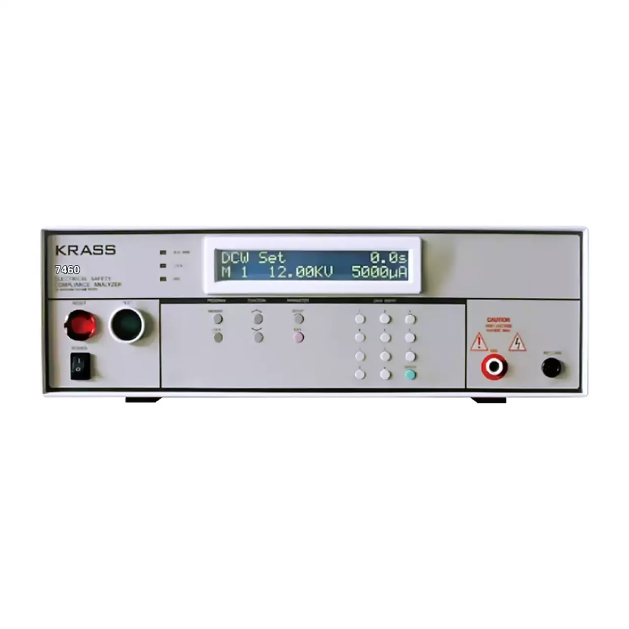
Benchtop high voltage tester seen from the front, with a backlit two-line display at the upper centre, a red reset button and a green test button at the left, function keys and a numeric keypad beneath the display, and high voltage and return terminals at the right

7460 (2 models) · Electrical Safety Testers

10 kV Programmable Withstand Voltage Tester

Programmable high voltage withstand tester in an alternating and a direct version, with a regulated output, fifty linked program groups, arc detection and remote control.

AC output
0.00 to 10.00 kV at 10 mA, on 7460
DC output
0.00 to 10.00 kV at 5000 μA, on 7462
Voltage resolution
0.01 kV
Leakage limits, AC
Upper 0 to 10.0 mA, lower 0.1 to 10.0 mA
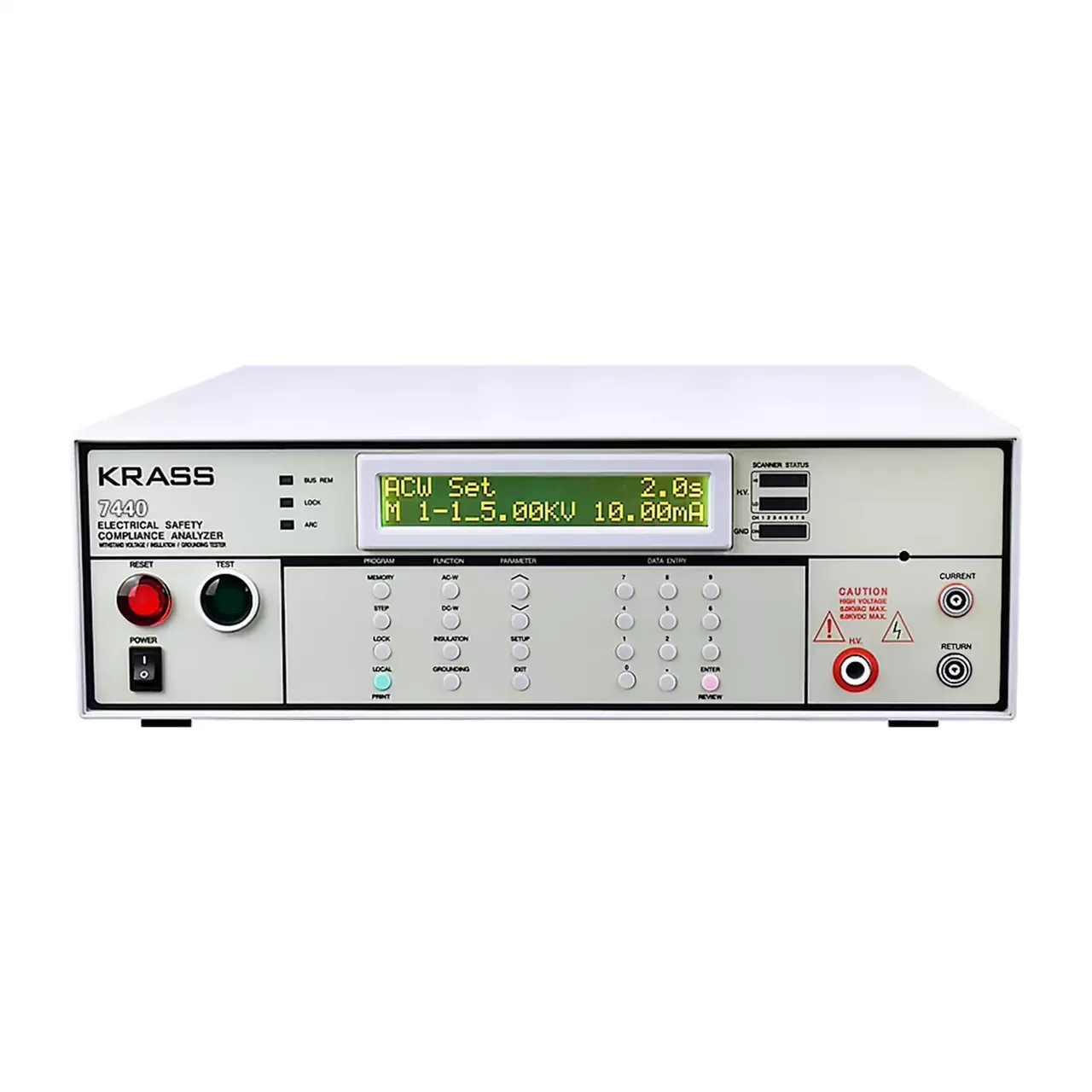
Benchtop safety compliance analyser seen from the front, with a backlit dot matrix display at the upper centre, a red reset button and a green test button at the left, function keys and a numeric keypad below the display, and current and return terminals at the right

7440 (4 models) · Electrical Safety Testers

Four-in-One Electrical Safety Compliance Tester

Bench safety compliance analyser combining AC and DC withstand, insulation resistance and, on the top model, ground bond testing, with stored programs and a matrix scanner interface.

AC withstand
0 to 5 kV, up to 40 mA
DC withstand
0 to 6 kV, up to 9999 μA
Insulation resistance
100 to 1000 V DC, 1 to 9999 MΩ
Ground bond
3 to 40 A, 0 to 600 mΩ, on 7440 only
Compact programmable safety tester shown from the front with the two-line LCD at the upper left, a row of function keys beneath it and the test terminals along the lower right

7110 (8 models) · Electrical Safety Testers

Compact AC/DC Withstand Voltage and Insulation Tester

Compact programmable safety tester with 5 kV AC and 6 kV DC withstand voltage, insulation resistance to 9999 MΩ, five stored programs and PLC remote control.

AC output
0 to 5.00 kV, 12 mA
DC output
0 to 6.00 kV, 5 mA, on four of the eight models
Frequency
50 or 60 Hz, selectable
Leakage limits
0.10 to 12.00 mA AC and 0.02 to 5.00 mA DC, upper and lower set independently

Request a quotation for the HG7804

Send the configuration you need and we will confirm availability, lead time and terms. Minimum order quantity is 1 pc.

Request for quotation

Request a quotation - HG7804

Send the technical detail and we will confirm availability, lead time and terms. In-stock items ship within 48 hours; customized specifications typically take 2-10 days. Minimum order quantity is 1 pc.

The more of this you can give us, the fewer exchanges are needed before we can quote.
No file chosen
Datasheet, drawing, BOM or photograph. One file, up to 10 MB (PDF, Office, image or ZIP).

By submitting this form you agree that we may contact you about this enquiry. We do not sell or share enquiry data. See our privacy policy.

Items held in stock are dispatched within 48 hours of order confirmation. Customized specifications are produced to order and typically ship within 2 to 10 days. Transit time then depends on the shipping method and destination.

Request a Quote WhatsApp