Electrical Test & Measurement · Electrical Test Equipment

Charge and Discharge Battery Simulator

Linear battery simulator in two ranges, 20 V at 10 A or 10 V at 2 A, with automatic changeover between charge and discharge, microamp readback and a 4.3-inch touchscreen.

CH906A (2 models) ·

Key specifications

Discharge voltage
0.1 to 20 V on CH906A; 0.1 to 10 V on CH906D
Discharge current
0 to 10 A on CH906A; 0 to 2 A on CH906D
Charge voltage
0.2 to 20 V on CH906A; 0.2 to 10 V on CH906D
Charge current
Up to 10 A below 10 V and 5 A above on CH906A; up to 2 A on CH906D
Setting resolution
1 mV up to 5 V and 5 mV above on CH906A; 1 mV on CH906D; 1 mA on current
Current readback resolution
0.0001 mA on the low range; 0.1 mA on the high range
Voltage accuracy
0.05% + 2 mV up to 5 V; 0.05% + 10 mV above 5 V on CH906A
Ripple
60 mV maximum
Display
4.3-inch TFT touchscreen with keypad and knob
Body
230 mm deep × 350 mm wide × 88 mm high

A product that charges and discharges is tested from both ends, and the change from one to the other is where the interesting behaviour sits. A simulator that has to be switched between the two modes cannot show what happens at the crossing. This range is built so that the crossing happens by itself.

Product overview

Two models share one control system and one body. CH906A reaches 20 V and 10 A on discharge; CH906D reaches 10 V and 2 A. Both present the same behaviour at the terminals: they hold a set voltage and pass current in either direction, and the changeover between charging and discharging is automatic.

The output stage is linear, which is the reason the ripple figure is as low as it is and also the reason the larger model weighs about seven kilograms. The front panel carries a 4.3-inch touchscreen, a numeric keypad, a knob and function keys, so a value can be typed or dialled. The rear carries the remote sense terminals, the serial port and the voltage selector.

How the battery simulator works

The instrument regulates its output to a set voltage and measures the current that flows. When the device under test draws current, the instrument supplies it and the device is being discharged. When the device returns current, the instrument absorbs it and the device is being charged. There is no mode to select, and no discontinuity at the point where the current passes through zero.

That matters for a product that manages its own charging. A phone, an earphone or a power bank does not simply stop drawing current at a fixed point; it negotiates, pulses and backs off. An instrument that holds a voltage and follows the current in both directions reproduces what a cell would do, without the cell’s own state of charge interfering with the test.

The remote sense connection is what keeps the delivered voltage honest. The sense leads measure at the product, and the regulator corrects for the drop in the current leads, which on a 10 A output is not negligible.

How to select the right battery simulator

The voltage window decides the model, and the window has two ends. A 12 V product needs CH906A because its charge voltage sits above 10 V; a single-cell product is covered by either, and CH906D is the smaller and lighter choice.

The current decides the rest. A product that draws 3 A in operation and returns 1 A while charging needs headroom on the discharge side, and the charge current limit matters if the test is meant to reproduce a fast charge rather than a slow one.

The third question is whether the test is driven from a computer. Both models carry an isolated RS232C port with SCPI commands, which allows the panel to be bypassed entirely, and that is the difference between a bench instrument and a component in a test system. If the sequence is written in software, the command set should be reviewed before the order rather than after.

The fourth question is the mains supply at the site. The instrument is ordered for one voltage or the other, not for a wide range, and the marking beside the inlet should be read before it is connected. Send the voltage window, the current in both directions and the intended control method, and a model can be proposed.

Measurement limitations and selection considerations

The voltage resolution and accuracy are specified in two bands, and the boundary sits at 5 V. On CH906A the resolution relaxes from 1 mV to 5 mV above that point, and the accuracy term grows with it. A test that depends on millivolt-level resolution at 12 V is therefore asking for something the printed specification does not offer.

The charge current limits are printed in more than one form, and they do not agree at the boundary. Until the supplier confirms which applies, the conservative reading is the one that limits current above 10 V, and a test plan should not be built around the higher figure.

Ripple is quoted as a maximum without a test condition or a bandwidth. That is enough to compare this range with another instrument quoted the same way, and not enough to predict the noise at a particular load; a bench that needs that figure should measure it in place.

The environmental limits are absent from the material. Operating temperature and humidity are not stated for either model, so a bench in an uncontrolled space should have those confirmed before the instrument is installed rather than assumed from the laboratory conditions the accuracy figures were probably taken in.

Features

  • Charge and discharge through one output, with the changeover between them automatic rather than switched by the operator
  • A linear output stage, which is the reason the ripple figure is quoted at 60 mV rather than at a switching frequency
  • Current readback that resolves 0.0001 mA on its low range, for standby current on a finished board
  • Six stored voltage and current settings recalled with a single key, for a bench that repeats the same few tests
  • Remote sense terminals on the rear panel, so the lead drop is taken out of the delivered voltage
  • An electrically isolated RS232C port with SCPI commands, for control from a computer or a PLC
  • USB host for exporting data and for updating the firmware without returning the instrument
  • A 4.3-inch touchscreen combined with a keypad and a knob, so a setting can be entered either way
  • A 350 mm width described as a standard rack size, for mounting into a system

Technical specifications

Every value below is taken from source documentation. Where a parameter is not stated in the available material it is marked as information required rather than estimated.
Discharge output
Voltage, CH906A0.1 to 20 VStandard
Voltage, CH906D0.1 to 10 VStandard
Current, CH906A0 to 10 AStandard
Current, CH906D0 to 2 AStandard
Charge input
Voltage, CH906A0.2 to 20 VStandard
Voltage, CH906D0.2 to 10 VStandard
Current, CH906A, parameter table0 to 10 A from 0.1 to 10 V; 0 to 5 A from 0.01 to 20 V, both voltage limits printed as they standStandard
Current, CH906A, selection table10 A at or below 10 V; 5 A above 10 VStandard
Current, CH906D0 to 2 AStandard
ChangeoverAutomatic between charge and discharge, without a stepStandard
Setting and readback
Voltage setting resolution, CH906A1 mV from 0.1 to 5 V; 5 mV from 5.01 to 20 VStandard
Voltage setting resolution, CH906D1 mVStandard
Current setting resolution1 mAStandard
Voltage setting accuracy, CH906A0.05% + 2 mV from 0.1 to 5 V; 0.05% + 10 mV from 5.01 to 20 VStandard
Voltage setting accuracy, CH906D0.05% + 2 mVStandard
Voltage readback resolution, CH906A1 mV from 0.1 to 5.0 V; 5 mV from 5.01 to 20 VStandard
Voltage readback resolution, CH906D1 mVStandard
Current readback resolution, CH906A0.0001 mA from 0 to 10 mA; 0.1 mA from 10 mA to 10 AStandard
Current readback resolution, CH906D0.0001 mA from 0 to 10 mA; 0.1 mA from 10 mA to 2 AStandard
Voltage readback accuracy, CH906A0.05% + 2 mV from 0.1 to 5 V; 0.05% + 10 mV from 5.01 to 20 VStandard
Current readback accuracy, CH906A0.1% + 1 µA on the low range; 0.1% + 3 mA on the high rangeStandard
Current readback accuracy, CH906D0.1% + 1 µA on the low range; 0.1% + 3 mA on the high rangeStandard
Voltage load regulationBelow 0.06%Standard
Voltage line regulationBelow 0.05%Standard
Display resolution1 mV on voltage, 1 µA on currentStandard
Interfaces
USB hostStandard, for data export and firmware updateStandard
SerialElectrically isolated RS232C, with SCPI commands and selectable baud ratesStandard
Remote senseS+ and S− terminals on the rear panelStandard
Stored presetsSix voltage and current settings, recalled with one keyStandard
Supply and environment
Mains voltage, parameter table110 or 220 V AC, shared by both modelsStandard
Rear panel marking~100 V, 50 or 60 Hz, as silkscreened beside the inletStandard
Ripple60 mV maximum, with no test condition statedStandard
Operating temperatureNot stated in the materialInformation required
Operating humidityNot stated in the materialInformation required
Mechanical
Dimensions230 mm deep, 350 mm wide, 88 mm high, shared by both modelsStandard
Rack width350 mm, described as a standard rack sizeStandard
Weight, CH906AAbout 7 kgStandard
Weight, CH906DAbout 4 kgStandard

Available models

Selection table
Model Configuration Key ranges Availability
CH906A 20 V, 10 A class Discharge 0.1 to 20 V at 0 to 10 A; charge 0.2 to 20 V The larger of the two, about 7 kg
CH906D 10 V, 2 A class Discharge 0.1 to 10 V at 0 to 2 A; charge 0.2 to 10 V The smaller of the two, about 4 kg

Customization

  • Mains voltage set for 110 or 220 V AC at the order stage
  • Test leads terminated for a particular fixture
  • Remote control sequences written against the SCPI command set

Certification and compliance

Certification documents not yet supplied

Certifications are only published once a certificate copy can be produced, so this section is deliberately empty rather than populated with assumed approvals. Tell us which approvals your application requires and we will confirm what is available for this instrument.

Parameters still to be confirmed

The following are required for a complete specification but are not stated in the documentation supplied to us. They are listed rather than estimated:

  • The operating temperature range, which the material does not give
  • The operating humidity range, which the material does not give
  • Which of the three printed forms of the CH906A charge current is correct, since the parameter table gives two voltage limits and the selection table gives one
  • Whether the second block is labelled input (charging) or input (discharging), as the two tables differ
  • The ripple test condition and bandwidth, since 60 mV is quoted without either
  • The mains voltage arrangement, given as 110 or 220 V AC in the table and marked ~100 V, 50 or 60 Hz beside the inlet
  • The current readback resolution for CH906D on the low range, where the selection table cell is obscured and only the parameter table gives a figure
  • The warm-up time and temperature conditions that apply to the accuracy figures, which are not stated
  • Calibration certificate availability and the standard it is issued against
  • Warranty period and terms

Frequently asked questions

What does the automatic changeover between charge and discharge mean in practice?

The instrument does not have a charge mode and a discharge mode that the operator selects. It holds a set voltage and lets current pass in whichever direction the device under test demands, so a product that draws current is being discharged from the simulator and a product that returns current is charging it. The current reading carries the direction.

Which model covers a 12 V product?

Neither, at the top of its range. CH906A reaches 20 V and CH906D stops at 10 V, so a 12 V product needs CH906A. Choosing a model whose maximum equals the product's nominal voltage leaves no headroom for the charging voltage, which is higher than the nominal figure.

Why does the voltage resolution change above 5 V?

On CH906A the resolution and the accuracy are both specified in two bands, one from 0.1 to 5 V and one from 5.01 to 20 V. The finer figure applies only in the lower band, so a measurement at 12 V should be judged against the second band rather than the first.

What has to be confirmed before a quotation?

The product's voltage and the current it draws and returns, the standby current the test has to resolve, and the mains voltage at the site, since the instrument is ordered for 110 or 220 V AC rather than for a wide range. Whether the test will be driven over the serial port also matters, as that decides the cabling.

Related products

Other models in the same range

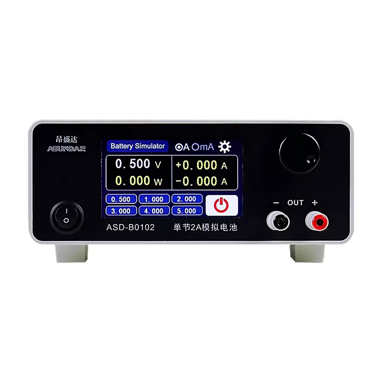
Small black bench instrument with a colour display reading 0.500 V and zero current, six blue preset voltage keys beneath it, a power switch at the lower left, a round knob at the upper right and a pair of red and black output terminals on the right

B0102 (3 models) · Electrical Test Equipment

Battery Simulator for Protection Board Testing

Bidirectional battery simulator range from 5 V to 60 V, sinking and sourcing current at the same terminals, with microamp current resolution and six stored voltages.

Voltage range
0 to 5 V on B0102; 0 to 20 V on 906B; up to 60 V on the 906 variants
Current range
0 to 2 A on B0102; 0 to 12 A on 906B; up to 30 A on the 906 variants
Power range
0 to 10 W on B0102; 0 to 240 W on 906B; up to 500 W on the 906 variants
Setting resolution
1 mV on voltage, 1 mA on current
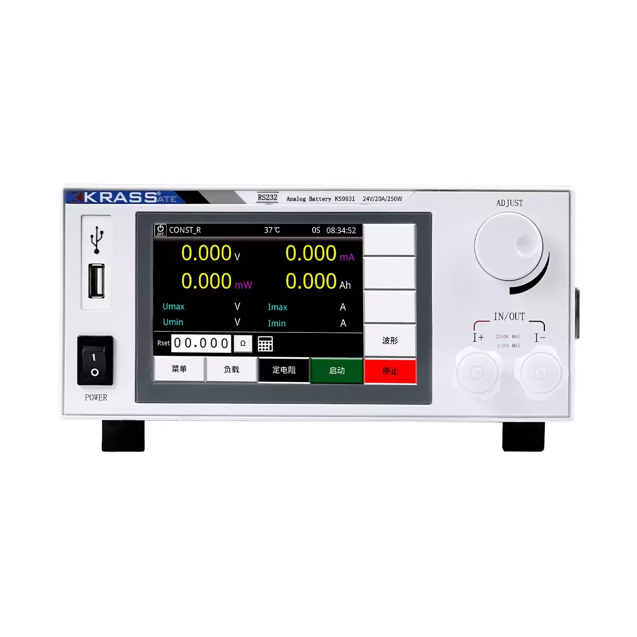
Bench instrument with a light grey case and black front panel, a colour display showing four large zero readings above five soft keys, a row of status values beneath, a single large adjustment knob at the upper right and a pair of output terminals marked IN and OUT at the lower right

KS9830 (5 models) · Electrical Test Equipment

Battery Simulator Power Supply

Five-model battery simulator range covering 20 to 48 V and up to 20 A, with 1 mV and 1 mA setting resolution, four-wire remote sensing and readback of voltage, current and power.

Output voltage
0 to 20 V on KS9830; 0 to 24 V on KS9831 and KS9831A; 0 to 48 V on KS9832 and KS9832A
Output current
0 to 12 A on KS9830; 10 or 20 A switchable on the other four
Output power
0 to 240 W on KS9830, KS9831 and KS9831A; 0 to 450 W on KS9832 and KS9832A
Setting resolution
1 mV on voltage, 1 mA on current

Request a quotation for the CH906A

Send the configuration you need and we will confirm availability, lead time and terms. Minimum order quantity is 1 pc.

Request for quotation

Request a quotation - CH906A

Send the technical detail and we will confirm availability, lead time and terms. In-stock items ship within 48 hours; customized specifications typically take 2-10 days. Minimum order quantity is 1 pc.

The more of this you can give us, the fewer exchanges are needed before we can quote.
No file chosen
Datasheet, drawing, BOM or photograph. One file, up to 10 MB (PDF, Office, image or ZIP).

By submitting this form you agree that we may contact you about this enquiry. We do not sell or share enquiry data. See our privacy policy.

Items held in stock are dispatched within 48 hours of order confirmation. Customized specifications are produced to order and typically ship within 2 to 10 days. Transit time then depends on the shipping method and destination.

Request a Quote WhatsApp