Electrical Test & Measurement · Electrical Test Equipment

Battery Simulator for Protection Board Testing

Bidirectional battery simulator range from 5 V to 60 V, sinking and sourcing current at the same terminals, with microamp current resolution and six stored voltages.

B0102 (3 models) ·

Key specifications

Voltage range
0 to 5 V on B0102; 0 to 20 V on 906B; up to 60 V on the 906 variants
Current range
0 to 2 A on B0102; 0 to 12 A on 906B; up to 30 A on the 906 variants
Power range
0 to 10 W on B0102; 0 to 240 W on 906B; up to 500 W on the 906 variants
Setting resolution
1 mV on voltage, 1 mA on current
Voltage setting accuracy
0.05% + 2 mV
Current readback resolution
1 µA below 10 mA; 1 mA at or above 10 mA
Current readback accuracy
0.15% + 5 µA below 10 mA; 0.15% + 4 mA from 10 mA to 10 A
Stored voltages
Six presets, set at the touchscreen
Ripple
100 mV peak to peak
Display
3.5-inch touchscreen

A protection board is a switch with a memory of two limits. Testing it means pushing the cell it protects past both limits and watching the switch open. Doing that with a real cell is slow, hard to repeat and, on an over-charge test, not entirely safe. A simulator replaces the cell with something that can be driven to either limit on demand.

Product overview

The range is three families. B0102 is a single-cell simulator in a small body. 906B is a 20 V, 12 A model with programmable automatic testing. The 906 family covers the rest of the range in fixed variants from 20 V to 60 V and from 200 W to 500 W.

All of them work in two directions at the same terminals. Current flows out when the instrument sources, and in when it sinks, and the current reading carries a sign so that the direction is visible rather than assumed. That single arrangement is what allows a charge test and a discharge test to be run on one connection.

How the battery simulator works

The instrument regulates its terminals to a set voltage, then delivers or absorbs whatever current the device asks for, up to its limit. When the device under test stops drawing, the instrument sources; when the device pushes current back, the instrument sinks it and the reading goes negative. From the device’s point of view it is connected to a cell that never runs flat and never over-charges.

Protection testing uses that behaviour directly. For an over-charge test the voltage is raised until the board’s protection trips, and the point at which the current falls to zero marks the trip. For an over-discharge test the voltage is lowered until the board disconnects its output. Both are read on the same display, and both are repeatable in a way that a real cell is not.

The microamp resolution matters for a different test. A finished board in standby draws very little, and the readback resolution changes at 10 mA: below that figure it resolves 1 µA, above it 1 mA. That break is deliberate, because a bench checking standby current and a bench checking working current need different resolutions.

How to select the right battery simulator

The voltage range of the pack sets the family. A single cell is served by B0102; a 20 V product by 906B or the 20 V variant; a 48 V or 60 V pack needs the corresponding high-voltage variant. Choosing at the top of a range leaves nothing for a pack that charges above its nominal figure.

The current sets the variant within the family. The 906 range trades current against voltage, so a 36 V product that draws 20 A needs the 400 W variant rather than the 300 W one, and the difference is not an option on a single unit.

The third question is whether the test has to run itself. Programmable automatic testing is offered on 906B only, and it is what turns a sequence of voltage steps and trip checks into something an operator starts and walks away from. If the bench runs one product with a fixed sequence, that matters; if every test is set by hand, it does not.

Finally, decide how fine the current reading has to be at the low end. The resolution steps at 10 mA across the whole range, so a standby measurement and a working-current measurement are both covered, but the accuracy figures in the two bands are different and should be checked against the tolerance the test requires. Send the pack voltage, the trip current and the standby current, and a variant can be proposed.

Measurement limitations and selection considerations

The current reading accuracy is printed in two bands, and the upper band stops at 10 A. On the variants that deliver 12, 20 or 30 A, the accuracy above 10 A is not covered by the figure in the material and has to be confirmed before the instrument is used to characterise a load in that region.

The rear socket and the mains specification do not agree. The socket is marked for a single voltage and frequency while the parameter table gives a wide input range, so the marking on the unit supplied should be read before it is connected to a supply at either end of the range.

The dimension drawing and the parameter table give different figures for the smallest model, and one of the tables in the material has lost its column header. Neither can be resolved from the material, so the fixture and the bench space should be planned against the larger of the figures until the supplier confirms which is correct.

Finally, the six stored voltages are presets at the panel, not a test sequence. A test that has to move between voltages in a defined order and record the result at each point is a programmable sequence, which is a different model in this range.

Features

  • One set of terminals that both sources and sinks current, so a protection board can be charged and discharged without reconnecting it
  • Microamp current resolution below 10 mA, which is what a standby current measurement on a finished board needs
  • Over-charge and over-discharge protection testing, the two trips a battery protection board exists to provide
  • Six stored voltages, so a test sequence can step between the points a protection board is specified at without entering each one
  • A 3.5-inch touchscreen with direct parameter entry, on a body small enough for a bench beside the fixture
  • Programmable automatic testing on 906B, for a sequence that has to repeat without an operator at the panel
  • Bidirectional readback with a signed current value, so charge and discharge are distinguished rather than inferred
  • Eight variants from 10 W to 500 W, so the same control behaviour is available at a range of product sizes

Technical specifications

Every value below is taken from source documentation. Where a parameter is not stated in the available material it is marked as information required rather than estimated.
Output and input
Voltage, B01020 to 5 VStandard
Voltage, 906B0 to 20 VStandard
Voltage, 906 variants0 to 20 V, 0 to 25 V, 0 to 36 V, 0 to 48 V or 0 to 60 V, depending on variantStandard
Current, B01020 to 2 AStandard
Current, 906B0 to 12 AStandard
Current, 906 variants0 to 10 A, 0 to 20 A or 0 to 30 A, depending on variantStandard
Power, B01020 to 10 WStandard
Power, 906B0 to 240 WStandard
Power, 906 variants0 to 200 W, 0 to 250 W, 0 to 300 W, 0 to 400 W or 0 to 500 W, depending on variantStandard
DirectionBidirectional; the current reading carries a sign to show charge or dischargeStandard
Setting and readback
Voltage setting resolution1 mVStandard
Current setting resolution1 mAStandard
Voltage setting accuracy0.05% + 2 mVStandard
Current setting accuracyNot stated in the material; only the voltage row is printedInformation required
Voltage readback resolution1 mVStandard
Current readback resolution1 µA below 10 mA; 1 mA at or above 10 mAStandard
Voltage readback accuracy0.05% + 2 mVStandard
Current readback accuracy0.15% + 5 µA below 10 mA; 0.15% + 4 mA from 10 mA to 10 AStandard
Voltage load regulationBelow 0.1%Standard
Voltage line regulationBelow 0.1%Standard
Ripple100 mV peak to peakStandard
Protection functions
Over-charge protection testSupportedStandard
Over-discharge protection testSupportedStandard
Programmable automatic testSupported on 906BStandard
Standby current measurementSupported to microamp resolutionStandard
Interfaces and controls
Display3.5-inch touchscreen with direct parameter entryStandard
Stored voltagesSix presetsStandard
Output terminalsRed OUT + and black OUT − binding postsStandard
Front panelDisplay, adjustment knob, power switch and terminalsStandard
Supply and environment
Mains input100 to 240 V AC, 50 to 60 HzStandard
Inlet markingAC220V 50HZ, as printed above the rear socketStandard
Operating temperature0 to 40 °CStandard
Humidity80% maximum, indoor use, without condensationStandard
CoolingFan, 60 × 60 × 25 mmStandard
Mechanical
Dimensions, B0102, parameter table256 mm × 211 mm × 104 mmStandard
Dimensions, B0102, dimension drawing313 mm × 123 mm × 315 mm, which does not match the tableInformation required
Dimensions, 906B300 mm deep × 220.5 mm wide × 97 mm highStandard
Weight, B01022.9 kgStandard
Weight, 906B5 kgStandard
Packaged weight3.5 kg for B0102; 5.6 kg for 906BStandard

Available models

Selection table
Model Configuration Key ranges Availability
B0102 Single-cell simulator, 5 V class 0 to 5 V, 0 to 2 A, 0 to 10 W Smallest body, 2.9 kg
906B Programmable automatic test, 20 V class 0 to 20 V, 0 to 12 A, 0 to 240 W The only variant with programmable sequences
906-20V10A200W 20 V class 0 to 20 V, 0 to 10 A, 0 to 200 W Wider current than 906B at lower power
906-25V20A250W 25 V class 0 to 25 V, 0 to 20 A, 0 to 250 W Mid range
906-36V10A300W 36 V class 0 to 36 V, 0 to 10 A, 0 to 300 W Higher voltage, lower current
906-36V20A400W 36 V class 0 to 36 V, 0 to 20 A, 0 to 400 W Higher voltage and current
906-48V30A500W 48 V class 0 to 48 V, 0 to 30 A, 0 to 500 W Highest current of the single-output variants
906-60V20A500W 60 V class 0 to 60 V, 0 to 20 A, 0 to 500 W Highest voltage

Customization

  • Output leads and clips suited to the fixture
  • Programmed test sequences stored on the 906B
  • Bench or shelf mounting for the body size ordered

Certification and compliance

Certification documents not yet supplied

Certifications are only published once a certificate copy can be produced, so this section is deliberately empty rather than populated with assumed approvals. Tell us which approvals your application requires and we will confirm what is available for this instrument.

Parameters still to be confirmed

The following are required for a complete specification but are not stated in the documentation supplied to us. They are listed rather than estimated:

  • The current setting accuracy, for which only the voltage row appears in the parameter tables
  • Which dimensions are correct for B0102, given 313 × 123 × 315 mm on the dimension drawing and 256 × 211 × 104 mm in the parameter table
  • Whether the 60 V variant is rated at 20 A and 500 W as its model code states, or at 60 A and 2000 W as one row of the multi-band table shows
  • The model assignment of the two columns in the size and weight table, whose header is cut off in the material
  • Whether the rear socket marked AC220V 50HZ accepts the 100 to 240 V AC range given in the table
  • The full list of supplied accessories, which the material does not give
  • Calibration certificate availability and the standard it is issued against
  • Warranty period and terms

Frequently asked questions

What makes a simulator suitable for protection board testing?

Two things: the ability to sink current as well as source it, and a current reading fine enough to see the board's own consumption. A protection board is tested by driving it into over-charge and over-discharge, which means the instrument has to act as a charger and as a load at the same terminals.

Can the same instrument measure standby current?

Yes, on the models described here. The current readback resolution is 1 µA below 10 mA, which is the region a finished board sits in when it is idle. The accuracy in that band is printed as a separate figure, so a measurement near the bottom of the range should be judged against that rather than against the accuracy at higher currents.

Which variant should be quoted for a 48 V pack?

The 906-48V30A500W variant, which covers 0 to 48 V at up to 30 A and 500 W. A pack that charges above 48 V needs the 60 V variant instead. The 906B is a fixed 20 V, 12 A, 240 W model and is chosen for its programmable sequences rather than for its range.

What has to be confirmed before a quotation?

The pack voltage and the current the protection board is expected to trip at, the standby current the test has to resolve, and whether the test sequence has to run automatically without an operator. The last point is the one that decides between 906B and the other 906 variants.

Related products

Other models in the same range

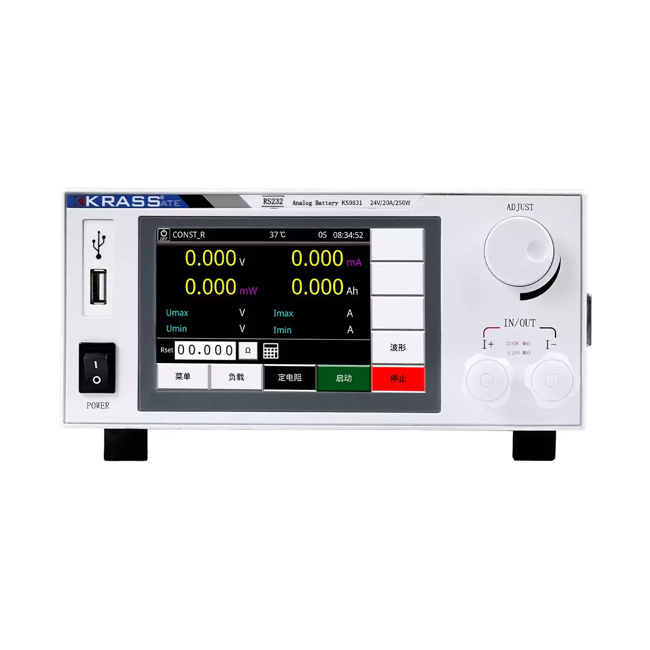
Bench instrument with a light grey case and black front panel, a colour display showing four large zero readings above five soft keys, a row of status values beneath, a single large adjustment knob at the upper right and a pair of output terminals marked IN and OUT at the lower right

KS9830 (5 models) · Electrical Test Equipment

Battery Simulator Power Supply

Five-model battery simulator range covering 20 to 48 V and up to 20 A, with 1 mV and 1 mA setting resolution, four-wire remote sensing and readback of voltage, current and power.

Output voltage
0 to 20 V on KS9830; 0 to 24 V on KS9831 and KS9831A; 0 to 48 V on KS9832 and KS9832A
Output current
0 to 12 A on KS9830; 10 or 20 A switchable on the other four
Output power
0 to 240 W on KS9830, KS9831 and KS9831A; 0 to 450 W on KS9832 and KS9832A
Setting resolution
1 mV on voltage, 1 mA on current
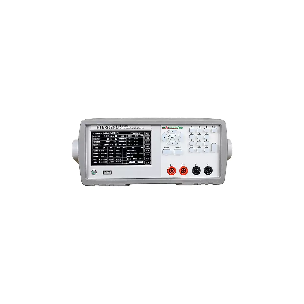
Light grey bench instrument with a liquid crystal display showing a table of battery readings on the left, a keypad with arrow keys and a numeric block on the right, and four terminals marked P+, R+, P- and R- along the lower right

HTB-2020 (2 models) · Electrical Test Equipment

Battery Capacity and Internal Resistance Tester

Two-model battery tester measuring voltage to 80 V, over-current to 20 A, internal resistance, identification resistance and capacity, with a built-in DC supply for charge and discharge.

Battery voltage range
0 to 20.000 V on HTB-2020; 0 to 80.000 V on HTB-2060, at 0.001 V
Over-current range
0 to 10.000 A on HTB-2020; 0 to 20.000 A on HTB-2060, at 0.001 A
Internal resistance
0 to 999.0 mΩ, resolution 0.1 mΩ
Identification resistance
0.1 to 999.9 kΩ, resolution 0.1 kΩ

Request a quotation for the B0102

Send the configuration you need and we will confirm availability, lead time and terms. Minimum order quantity is 1 pc.

Request for quotation

Request a quotation - B0102

Send the technical detail and we will confirm availability, lead time and terms. In-stock items ship within 48 hours; customized specifications typically take 2-10 days. Minimum order quantity is 1 pc.

The more of this you can give us, the fewer exchanges are needed before we can quote.
No file chosen
Datasheet, drawing, BOM or photograph. One file, up to 10 MB (PDF, Office, image or ZIP).

By submitting this form you agree that we may contact you about this enquiry. We do not sell or share enquiry data. See our privacy policy.

Items held in stock are dispatched within 48 hours of order confirmation. Customized specifications are produced to order and typically ship within 2 to 10 days. Transit time then depends on the shipping method and destination.

Request a Quote WhatsApp