- Output voltage
- 0 to 30 V, continuously adjustable
- Output current
- 0 to 3 A or 0 to 5 A, by model
- Setting accuracy
- 0.5% + 20 mV on voltage, 0.1% + 5 mA on current, at 25 ±5 °C
- Ripple
- 1 mVrms on voltage and 3 mArms on current, measured from 20 Hz to 20 MHz
- Load effect
- 0.01% + 2 mV on voltage, 0.02% + 5 mA on current
- Line effect
- 0.01% + 3 mV on voltage, 0.02% + 3 mA on current
- Resolution
- 10 mV and 1 mA, the same for setting and for readback
- Display
- Four-digit LED, separate voltage and current windows, with CV and CC lamps
- Stored settings
- Three groups recalled from M1, M2 and M3; not fitted on the T model
- Control interface
- USB programmable port on the P model only
A linear bench supply is a heavy answer to a simple question. The question is whether the output is clean enough that the measurement in front of it can be trusted, and the weight is the transformer that makes it so.
Product overview
Four models share one case, one panel and one output stage. They differ in current — three or five amps — in whether settings can be stored, and in whether the output can be driven from a computer. Voltage is the same across all four.
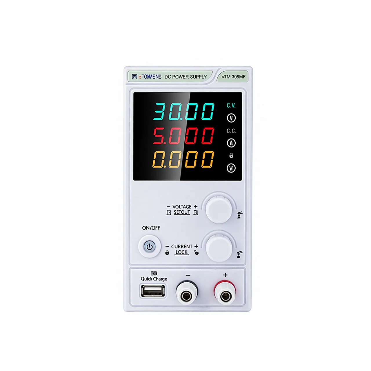
The front panel has two display rows, one for volts and one for amps, with a CV lamp and a CC lamp beside them. Below the display is a cluster of six keys: three for stored settings, one to choose which parameter is being set, one for overcurrent protection and one for the menu. A single shuttle knob adjusts the selected parameter, with fine and coarse ranges and a press-to-hold action. The output posts, negative, earth and positive, sit along the bottom right with the mains switch.
The rear carries the fan, the inlet, the fuse and, on the P model, a USB port. A folding handle on top is the reason the case can be carried between benches without a trolley.
How the adjustable DC power supply works
The mains is stepped down by a transformer, rectified, and then dropped across a pass transistor that is controlled by the error between the set value and the measured output. Because the regulation is dissipative rather than switched, there is no switching frequency to filter out, which is why the ripple figure is quoted in millivolts and the case is heavy.
The same loop serves both modes. When the load draws less than the set current, the supply regulates voltage and the CV lamp is lit. When the load asks for more, the loop regulates current instead, the voltage falls to whatever the load allows, and the CC lamp lights. The crossover is continuous, which is what makes the supply usable as a charging source as well as a voltage source.
Setting is done through the knob, with fine and coarse ranges covering the same span. Coarse moves quickly across the range; fine resolves the last millivolts. Three settings can be stored and recalled, which is useful where the same three tests repeat through a shift.
The output is read back at the terminals rather than inferred from the setting, so a lead with too much resistance or a supply that is being asked for more than it can give shows up as a difference between the two rows.
How to select the right supply
Decide the current first. Three amps covers small boards, sensors and most repair work; five amps covers motors, relays and devices with a start-up surge. The voltage is the same either way, so the current is the only decision on the output side.
Then decide whether settings need to be stored. Three groups on the front panel suit a bench that repeats a small set of tests; the T model drops them for a bench that sets the supply once and leaves it.
Then decide about control. The USB port on the P model is for a test script or a logging PC. It is a factory fitting, so it cannot be added later, and a bench that might grow into automated testing should take it now rather than replace the supply.
Finally, check the load’s behaviour at switch-on. A device with a large capacitor charges at the current limit, and a supply that is set to a low limit will take a long time to bring it up. Send the voltage, the current, whether the load is resistive or inductive, and whether a PC will drive the supply.
Measurement limitations and selection considerations
The accuracy figures are quoted at 25 ±5 °C. A bench beside a warm instrument or under a window will drift outside that band, and the temperature coefficient given in the table is the figure that then applies. Neither is a fault; it is how a linear supply behaves.
The ripple is quoted at the terminals over a wide bandwidth. A long lead adds inductance, and a load that switches quickly will see more disturbance than the figure suggests. Short, twisted leads do more for a sensitive load than another decimal place on the specification.
The current limit is a protection, not a measurement. When the CC lamp is lit the voltage row is no longer the set value, and a reading taken in that state describes the load rather than the supply.
Finally, the supply sources current and does not sink it. A battery or a charged capacitor connected to the terminals will push current back, and switching the output off does not disconnect the load. Where a charge has to be drawn out as well as put in, an electronic load is the instrument for the job, and this supply is not a substitute for one.
Every value below is taken from source documentation. Where a parameter is not stated in the available material it is marked as information required rather than estimated.