- Output voltage
- 15, 30, 60, 100 or 150 V maximum, by model
- Output current
- 2 to 20 A maximum, by model
- Readout
- Four-digit LED for voltage, current and power at the same time
- Setting resolution
- 10 mV below 100 V, 0.1 V at 100 V and above
- Setting accuracy
- 0.1% + 5 digits on voltage, 0.2% + 10 digits on current
- Ripple
- 10 mVrms on the 15 V and 30 V models, rising to 20 mVrms on the 150 V model
- Regulation
- Constant voltage and constant current, crossing automatically
- Protection
- Overvoltage, overcurrent, over-temperature and short circuit
- Mains
- AC 220 V ±10%, 50 Hz; 110 V input to order
- Body
- 80 × 150 × 230 mm, about 1.95 kg
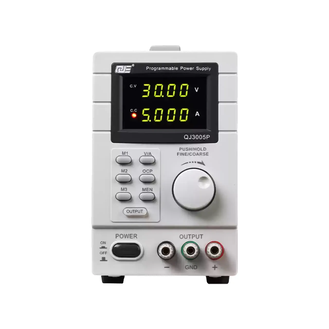
A repair bench has less room than a laboratory, and most bench supplies are built for the laboratory. This one is 80 mm wide, which is roughly the width of a phone lying down, and it still carries a four-digit display and two knobs.
Product overview
Eight models share one chassis and one control layout. They differ in maximum voltage and maximum current, and the pairing is not proportional: the range includes a 15 V unit at 20 A and a 150 V unit at 2 A, because those are the two shapes of work a bench actually sees.
The front panel holds a display with three rows, one each for voltage, current and power, with a C.V. and a C.C. indicator beside them and a lock indicator below. Two knobs set voltage and current, an ON/OFF key controls the output, and the positive and negative terminals sit at the bottom with an optional quick-charge USB socket between them.
The rear carries the mains switch, the fan, the inlet and the fuse, plus an RS-485 socket when that option is ordered. The case is ventilated on both sides and stands on four feet, so it can sit under a shelf rather than needing clear space above.
How the mini DC power supply works
The output stage holds one of two conditions. In constant voltage it regulates the terminal voltage to the set value and lets the current fall where it will; in constant current it regulates the current and lets the voltage fall. The crossover is automatic, and the two indicators tell the operator which condition is active — which is the single most useful piece of information on the panel when a device under test starts to draw more than expected.
Setting is done before the output is enabled. That is why there is no need to short the terminals to set a current limit, a routine that damages leads and startles the user in equal measure. The set values are held while the output is off, and the lock prevents them being moved by a hand brushing a knob.
The meter reads the output back rather than repeating the set value, so a sagging supply or a lead with too much resistance shows up as a difference between the two. Voltage and current are read at their own resolutions, and both are quoted with a warm-up condition, because a cold instrument drifts.
Cooling is proportional. The fan follows the output power, which keeps a lightly loaded supply quiet and only spins up when the heatsink needs it. On a bench where the supply runs all day at a fraction of its rating, that is the difference between a tolerable room and an irritating one.
How to select the right supply
Take the voltage and the current separately. A device that needs 12 V at 8 A is not served by a 30 V 5 A unit, and a device that needs 120 V at 200 mA is not served by a 30 V 20 A unit. The models are arranged along both axes for that reason.
Then look at the load. A resistive load is undemanding; a motor, a relay coil or a board with a large capacitor draws a surge at switch-on that the current limit will treat as a fault. Where that happens, the limit has to be set above the surge, not above the running current.
Consider the ripple figure at the voltage you intend to use. It rises across the range, and a supply chosen for its voltage headroom may be the noisiest option for a sensitive measurement. If the work is audio or sensor front-end, the lower-voltage models are the quieter ones.
Finally, decide the options at the order. The USB charging socket and the RS-485 port are factory fittings, and the mains configuration — fixed 110 V or a changeover — has to match the site. Send the voltage, the current, the nature of the load and the mains available, and a model can be proposed.
Measurement limitations and selection considerations
A four-digit display is not a four-digit measurement. The accuracy figure includes a digit count, and at the bottom of a range that count is a larger fraction of the reading than at the top. A 0.1 V setting on a 150 V unit is a coarse adjustment by design, not a fault.
The current limit protects the supply and the device, but it does not protect a device from itself. A board with a short will sit at the limit with the voltage collapsed, and nothing on the panel says whether that is a soft start or a fault. Reading the voltage row while the current row is pinned is the only signal available.
Ripple is quoted at the output terminals. A long lead with clip ends adds inductance and resistance, and a load that switches quickly will see more disturbance than the figure suggests. Twisted pairs and short leads do more for a sensitive load than a lower ripple specification.
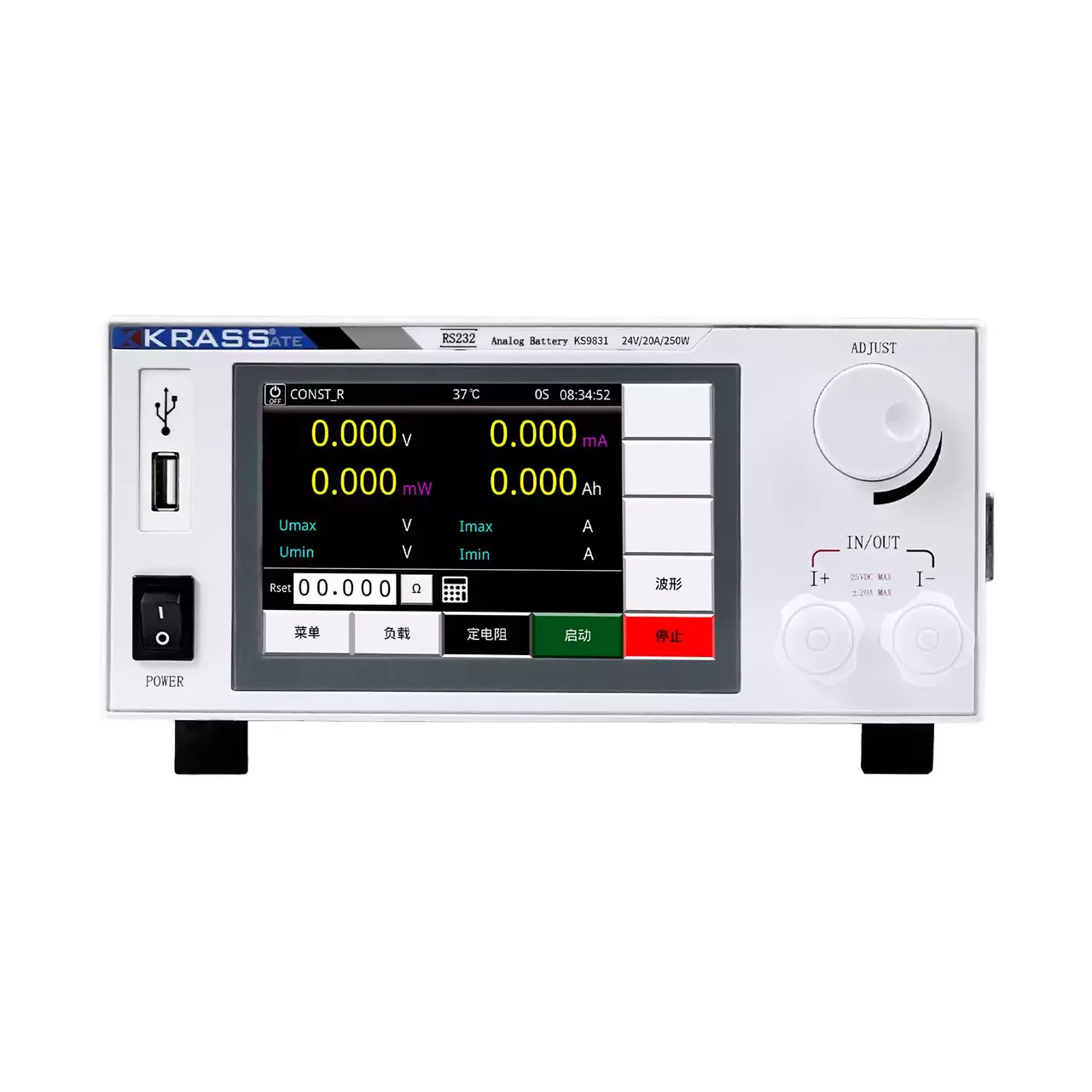
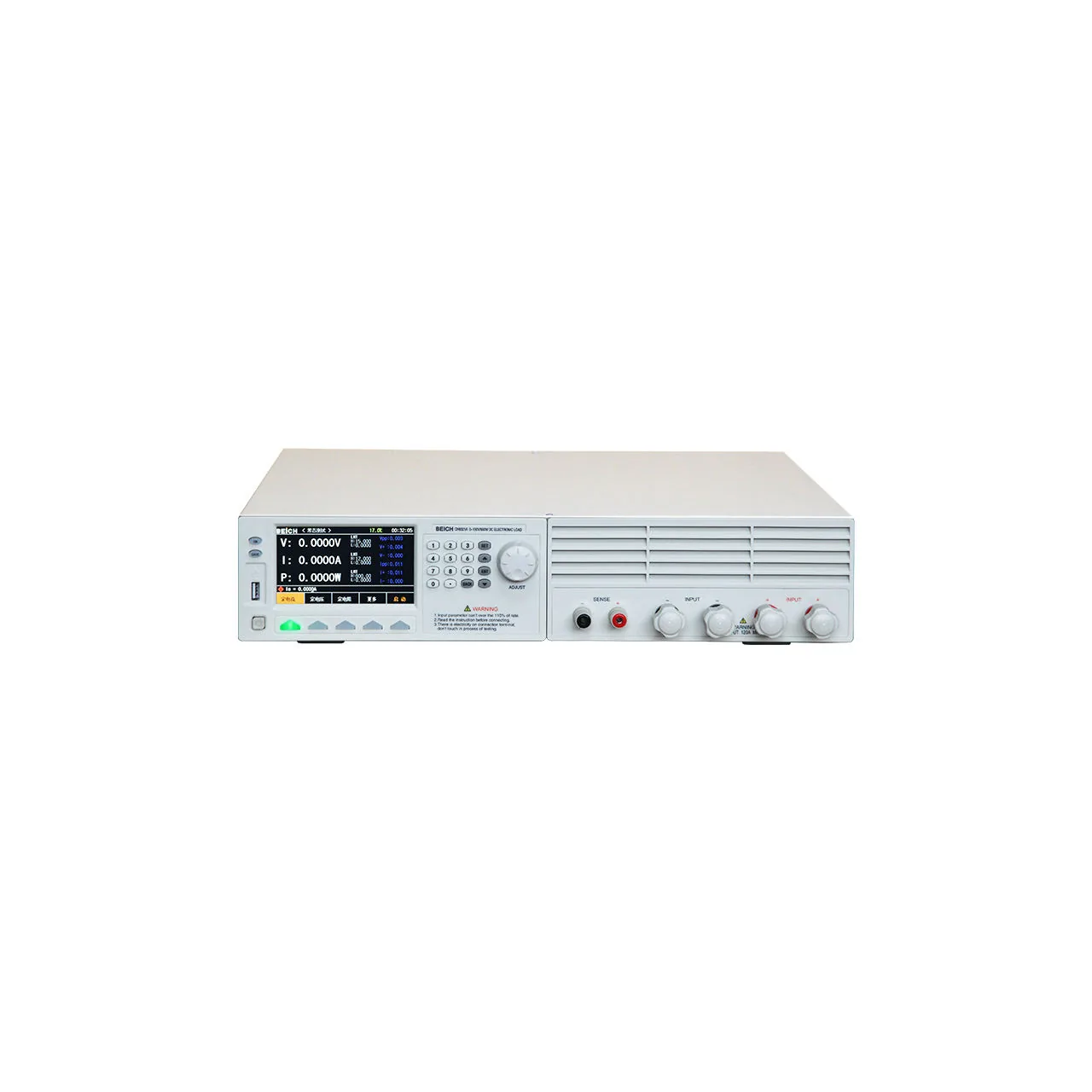
The supply is a two-quadrant source in the sense that it sources current only: it cannot sink. A battery or a charged capacitor connected to the terminals will push current back into the output, and a supply that is switched off with a charged load attached is not protected by its own limit. Where sinking matters, an electronic load is the instrument to reach for.
Every value below is taken from source documentation. Where a parameter is not stated in the available material it is marked as information required rather than estimated.