Electrical Test & Measurement · Electrical Test Equipment

Programmable DC Electronic Load

Programmable DC electronic load with 150 V and 500 V inputs, 60 to 240 A, 600 to 1500 W, six load modes and battery, dynamic and OCP test functions.

CH6321A (5 models) ·

Key specifications

Input voltage
0 to 150 V on four models; 0 to 500 V on four models
Input current
0.1 mA to 60 A, 120 A or 240 A depending on model
Input power
600 W, 900 W, 1200 W or 1500 W depending on model
Load modes
Constant voltage, constant current, constant power, constant resistance, short circuit and open circuit
Sampling
500 kHz analogue-to-digital conversion, with Vpp, Ipp, Vp+ and Vp- measured in real time
Dynamic test
Up to 50 kHz, with settable current slope and pulse width from 0.010 ms to 999 s
Battery test
Capacity to 9999 AH, discharge time to 4294967295 s, with internal resistance and curve plotting
Stored setups
100 internal and 500 external on a USB drive
Interfaces
RS232C, electrically isolated, with SCPI commands; USB host for data export and firmware
Body
430 × 88 × 450 mm

An electronic load is the instrument that lets a power supply be tested at the current it was designed for, without a bank of resistors and without the heat they produce. This range sinks up to 240 A or 500 V, in eight combinations of voltage, current and power, with the test functions a modern supply needs.

Product overview

Eight models divide into a 150 V class and a 500 V class. Within each class the power rises from 600 W to 1500 W, and the current rises with it, so a low-voltage bench can have 240 A while a high-voltage bench stops at 60 A or 120 A.

The front panel is a 4.3 inch colour screen with a numeric keypad, four soft keys and an adjustment knob, and the interface can be set to English or Chinese. The rear carries the input terminals, a current monitor, the RS232C connector and the voltage selector.

How the programmable DC electronic load works

The load is a power stage that sinks current from the source under test. In constant current mode it holds the current at the set value whatever the source voltage does; in constant voltage, constant resistance and constant power modes it holds that quantity instead, and in short and open modes it presents the two extremes.

The measurement is taken at the terminals, by a converter sampling at 500 kHz. That rate is fast enough to report peak-to-peak values and the positive and negative peaks, not just an average, which is how the ripple of a switching supply and the transient of a load step are seen rather than smoothed away.

Dynamic testing switches between two current levels at up to 50 kHz with a settable slope. It is the test that shows whether a supply recovers from a load step cleanly or rings, and the slope matters because a supply can pass a slow step and fail a fast one.

Battery mode discharges the pack at a set current to a cut-off voltage, integrating the current over time to report capacity, and recording internal resistance and a discharge curve along the way.

How to select the right programmable DC electronic load

The three ratings apply together, and the lowest one decides. A 48 V supply at 100 A is 4.8 kW, which no model here can sink; a 1500 W unit reaches only about 31 A at 48 V. Starting from the power rather than from the current avoids specifying an instrument that cannot run the test.

The second question is voltage. A 500 V model costs current for the same power, so it is the right choice only where the source has a high-voltage bus: a power-factor-corrected supply, an LED driver or a piece of equipment with a 400 V DC link.

The third is the test function. Battery discharge, dynamic stepping, OCP and list testing are all built in, so the choice is about which are needed rather than about add-ons. A bench that only checks steady-state regulation does not need the battery function; one that qualifies chargers needs all of them.

The fourth is recording. RS232C is standard and the PC software is optional, so a bench that logs results to a computer has to specify the software or write its own commands against the SCPI set.

Measurement limitations and selection considerations

The power rating is not available at every voltage and current. It is the product of the two, and the instrument reaches its power limit before its voltage or current limit at the extremes of the range. The derating curve matters at the top of the current range, and the material states that 120 A or 240 A is reached only under defined cooling conditions while the curve itself is not supplied.

The load dissipates everything it sinks as heat. At 1500 W the bench has to be able to remove that heat, and a unit installed in a rack with other equipment may not reach its rating. The installation conditions are part of the specification, not an afterthought.

The leads between the load and the source carry the full current and drop voltage. At 120 A a metre of ordinary cable drops a significant fraction of a volt, which appears as an error in the voltage reading and as a limit on the current actually reached. Four-terminal sensing at the load terminals is the reason the sense pair exists.

Finally, the load tests the source, not the product it powers. A supply that holds its voltage into a programmed current can still fail in the application, and the load’s job is to characterise the supply so that the application test can be designed.

Features

  • Eight models over two voltage classes and four power levels, so a 150 V bench and a 500 V bench can be specified from one family
  • Six load modes including open circuit, which is what a charger’s no-load behaviour needs alongside the usual constant current and constant resistance
  • 500 kHz sampling, fast enough to report peak-to-peak and positive and negative peaks rather than only an average
  • Dynamic testing to 50 kHz with a settable current slope, for the transient response of a power supply rather than its steady state
  • Battery mode that discharges to a set cut-off while recording capacity, internal resistance and a curve, with capacity to 9999 AH
  • OCP testing that finds the protection point and the maximum power point automatically and reports the voltage and current there
  • List testing of up to sixty steps with a comparator, so a sequence of load conditions produces one verdict rather than sixty readings
  • A hundred internal setups and five hundred on a USB drive, which is what a line with many products needs at changeover

Technical specifications

Every value below is taken from source documentation. Where a parameter is not stated in the available material it is marked as information required rather than estimated.
Input ratings
CH6321A0 to 150 V; 0.1 mA to 120 A; 600 WStandard
CH6321B0 to 150 V; 0.1 mA to 120 A; 900 WStandard
CH6322A0 to 150 V; 0.1 mA to 240 A; 1200 WStandard
CH6323A0 to 500 V; 0.1 mA to 60 A; 600 WStandard
CH6323B0 to 500 V; 0.1 mA to 60 A; 900 WStandard
CH6324A0 to 500 V; 0.1 mA to 120 A; 1200 WStandard
CH6325A0 to 500 V; 0.1 mA to 120 A; 1500 WStandard
CH6326A0 to 150 V; 0.1 mA to 240 A; 1500 WStandard
Accuracy
Voltage, 0 to 9.9999 V±(0.05% + 0.03% of full scale)Standard
Voltage, 10 to 99.999 V±(0.05% + 0.03% of full scale)Standard
Voltage, 100 V to full scale±(0.05% + 0.03% of full scale)Standard
Current, 0 to 9.9999 A±(0.05% + 0.05% of full scale)Standard
Current, 10 to 99.999 A±(0.05% + 0.05% of full scale)Standard
Current, 100 A to full scale±(0.05% + 0.05% of full scale)Standard
Constant resistance±(0.2% + 0.2% of full scale) over 0.05 to 5 Ω; ±(0.1% + 0.1% of full scale) over 0.5 to 500 Ω; ±(1% + 1% of full scale) over 500 Ω to 5 kΩStandard
Constant power±(0.1% + 0.1% of full scale) from 10 to 1500 WStandard
Resolution0.1 mV, 0.1 mA; display resolution to 0.0001Standard
Test functions
Battery test2 V to full-scale input; capacity to 9999 AH; discharge time 1 to 4294967295 s; internal resistance and curve plottingStandard
Dynamic testPulse width 0.010 ms to 999 s, edge resolution 0.010 ms, edge time 6 s, frequency up to 50 kHzStandard
List testUp to 60 steps, each 1 to 60000 s, any of the six load modes per step, with a comparator and an overall verdictStandard
OCP testAutomatically finds the protection point, the maximum power point and the voltage and current at that pointStandard
TimingOVP protection point and protection time; power-on and hold-up timeStandard
CR-LED modeA resistance mode configured for LED driver testingStandard
Ripple measurementVoltage and current peak-to-peak and positive and negative peaks, from the 500 kHz samplingStandard
Construction
Display4.3 inch TFT colour screen, English or Chinese interface, showing voltage, current, power and the set limits togetherStandard
Front panelScreen, numeric keypad, function keys, soft keys, adjustment knob, power switch and USB host portStandard
Rear panelVent, voltage selector, mains inlet, RS232C connector and input terminals including a current monitorStandard
Dimensions430 × 88 × 450 mmStandard
WeightNot stated in the materialInformation required
Supplied itemsMain unit, test report, warranty certificate, conformity certificate, mains lead and manual in electronic formStandard

Available models

Selection table
Model Configuration Key ranges Availability
CH6321A 150 V, 120 A, 600 W 0 to 150 V; 0.1 mA to 120 A; 600 W The entry model, and the one the material is written around
CH6321B 150 V, 120 A, 900 W 0 to 150 V; 0.1 mA to 120 A; 900 W The same voltage and current with more power
CH6322A 150 V, 240 A, 1200 W 0 to 150 V; 0.1 mA to 240 A; 1200 W The high-current 150 V model
CH6323A 500 V, 60 A, 600 W 0 to 500 V; 0.1 mA to 60 A; 600 W The entry model of the 500 V class
CH6323B 500 V, 60 A, 900 W 0 to 500 V; 0.1 mA to 60 A; 900 W 500 V with more power
CH6324A 500 V, 120 A, 1200 W 0 to 500 V; 0.1 mA to 120 A; 1200 W The middle of the 500 V class
CH6325A 500 V, 120 A, 1500 W 0 to 500 V; 0.1 mA to 120 A; 1500 W The largest 500 V model
CH6326A 150 V, 240 A, 1500 W 0 to 150 V; 0.1 mA to 240 A; 1500 W The largest current and power at 150 V

Customization

  • Test sequences written for a particular power supply or charger
  • A PC control package, which is an option rather than a supplied item
  • Leads and fixtures for a particular output connector

Certification and compliance

Certification documents not yet supplied

Certifications are only published once a certificate copy can be produced, so this section is deliberately empty rather than populated with assumed approvals. Tell us which approvals your application requires and we will confirm what is available for this instrument.

Parameters still to be confirmed

The following are required for a complete specification but are not stated in the documentation supplied to us. They are listed rather than estimated:

  • The weight of every model, which the material does not state
  • The derating curve at the top of the current range, which the material notes is not given but is needed to confirm that 120 A or 240 A is available continuously
  • Whether the resolution table applies to the 150 V models, since it is printed only on the page covering the 500 V models
  • The mains input voltage and frequency, which the material does not state
  • The operating temperature range and the cooling requirement at full power
  • The rating of the rear current monitor output
  • Whether a rack mounting kit is available
  • Calibration certificate availability and the standard it would be issued against
  • Warranty period and its terms
  • Ingress protection rating, which the material does not state

Frequently asked questions

Which model suits a 48 V, 100 A power supply?

CH6321A or CH6321B for a 150 V input at 120 A, with the power level deciding between them: 600 W and 900 W. A 48 V supply at 100 A delivers 4.8 kW, which is beyond any single model in this range, so a 1500 W unit would reach its power limit at about 31 A at 48 V. The power rating, not the current rating, is what limits this case.

What is the difference between the 150 V and the 500 V models?

The input stage. The 150 V models reach higher current for the same power, which suits battery packs, single-phase supplies and low-voltage adapters. The 500 V models reach 500 V but at lower current, which suits power-factor-corrected supplies, LED drivers and equipment with a high-voltage DC bus.

What has to be confirmed before a quotation?

The maximum voltage and current of the source under test, and the power it delivers, since the three limits apply together and the lowest one decides; whether the test needs dynamic or battery functions; and how the results are recorded, since the PC software is an option and the RS232C port is standard.

Related products

Other models in the same range

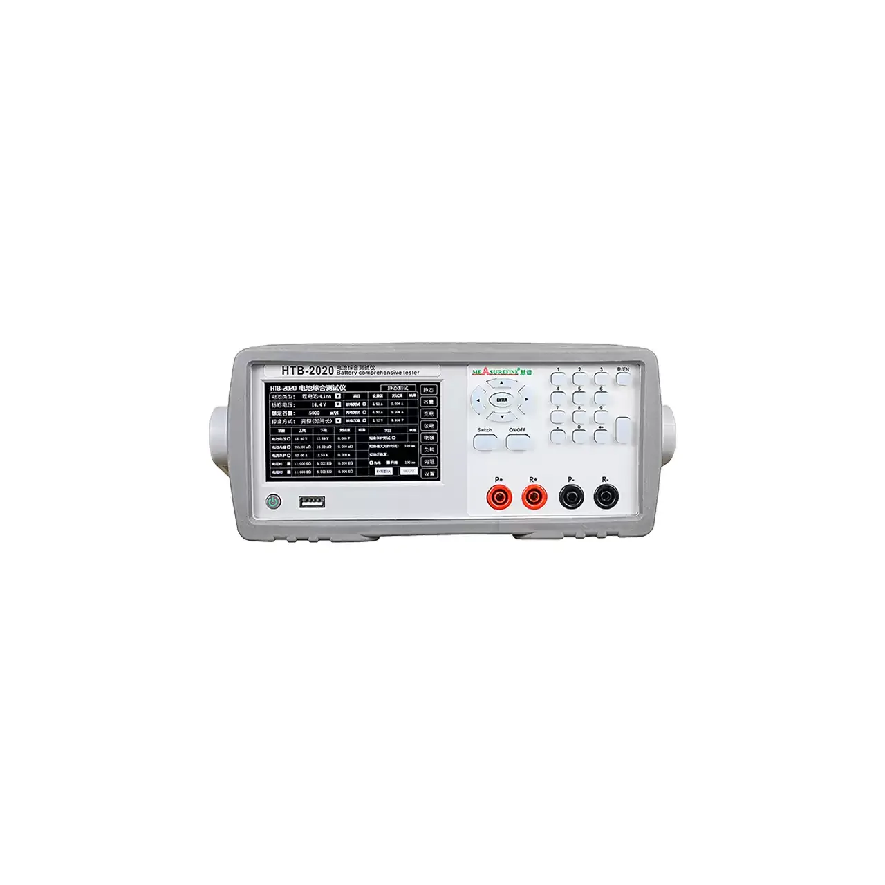
Light grey bench instrument with a liquid crystal display showing a table of battery readings on the left, a keypad with arrow keys and a numeric block on the right, and four terminals marked P+, R+, P- and R- along the lower right

HTB-2020 (2 models) · Electrical Test Equipment

Battery Capacity and Internal Resistance Tester

Two-model battery tester measuring voltage to 80 V, over-current to 20 A, internal resistance, identification resistance and capacity, with a built-in DC supply for charge and discharge.

Battery voltage range
0 to 20.000 V on HTB-2020; 0 to 80.000 V on HTB-2060, at 0.001 V
Over-current range
0 to 10.000 A on HTB-2020; 0 to 20.000 A on HTB-2060, at 0.001 A
Internal resistance
0 to 999.0 mΩ, resolution 0.1 mΩ
Identification resistance
0.1 to 999.9 kΩ, resolution 0.1 kΩ
Benchtop digital power meter in a pale case, front view with a wide black display showing four stacked numeric lines against the A, B, C and D channel labels, and a keypad with a rotary confirm control to the right of the display

YP9901 (3 models) · Power Meters

Single-Phase Digital Power Meter

Panel digital power meter reading voltage, current, active power, power factor, frequency, apparent and reactive power in four windows at once, with an RS232 Modbus RTU port as standard and current ratings from 20 A to 200 A.

Basic accuracy
±0.2 % (0.2 class)
Measurement mode
AC on the AC series; AC, DC and RMS on the AC/DC series
Voltage input
3 to 600 V AC; 3 to 600 V AC + DC on the AC/DC series
Current ranges
5 mA to 20 A up to 50 mA to 200 A, according to series and rating
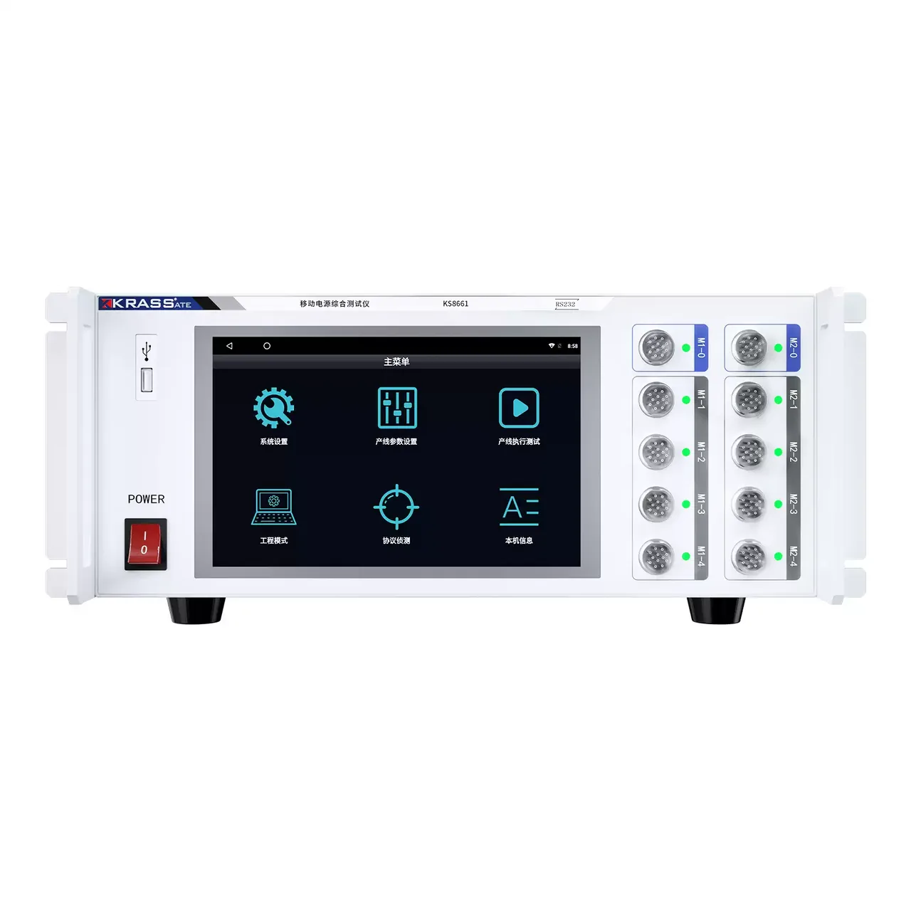
White bench instrument with a 10-inch touchscreen showing a menu of six icons, a power switch and a USB socket on the left, and ten round multi-pin test sockets in two vertical columns labelled M1-0 to M1-4 and M2-0 to M2-4 on the right

KS8661 · Electrical Test Equipment

Power Bank Comprehensive Tester

Ten-port bench tester for power banks, adapters and storage supplies, with a built-in electronic load, 20 V and 10 A per port, 200 W and a 10-inch touchscreen.

Maximum test voltage
20 V
Maximum test current
10 A
Maximum test power
200 W
Channel arrangement
Four modules, ten ports

Request a quotation for the CH6321A

Send the configuration you need and we will confirm availability, lead time and terms. Minimum order quantity is 1 pc.

Request for quotation

Request a quotation - CH6321A

Send the technical detail and we will confirm availability, lead time and terms. In-stock items ship within 48 hours; customized specifications typically take 2-10 days. Minimum order quantity is 1 pc.

The more of this you can give us, the fewer exchanges are needed before we can quote.
No file chosen
Datasheet, drawing, BOM or photograph. One file, up to 10 MB (PDF, Office, image or ZIP).

By submitting this form you agree that we may contact you about this enquiry. We do not sell or share enquiry data. See our privacy policy.

Items held in stock are dispatched within 48 hours of order confirmation. Customized specifications are produced to order and typically ship within 2 to 10 days. Transit time then depends on the shipping method and destination.

Request a Quote WhatsApp