- Maximum test voltage
- 20 V
- Maximum test current
- 10 A
- Maximum test power
- 200 W
- Channel arrangement
- Four modules, ten ports
- Voltage and current accuracy
- ±(0.05% + 0.05 FS), as printed
- Resolution
- 0.5 mV on voltage, 0.5 mA on current
- Protocols
- QC2.0, QC3.0, PD2.0, PD3.0 and PD3.1; AFC, FCP, SCP and SSCP optional
- Load modes
- Constant current or constant voltage
- Display
- 10-inch touchscreen
- Body
- 487.6 × 181 × 450 mm
A power bank is a charger and a battery in one housing, and the port is where both are judged. The instrument that tests it therefore has to do two things at once: act as the device the port is trying to charge, and hold a load long enough to see whether the output stays inside its own specification.
Product overview
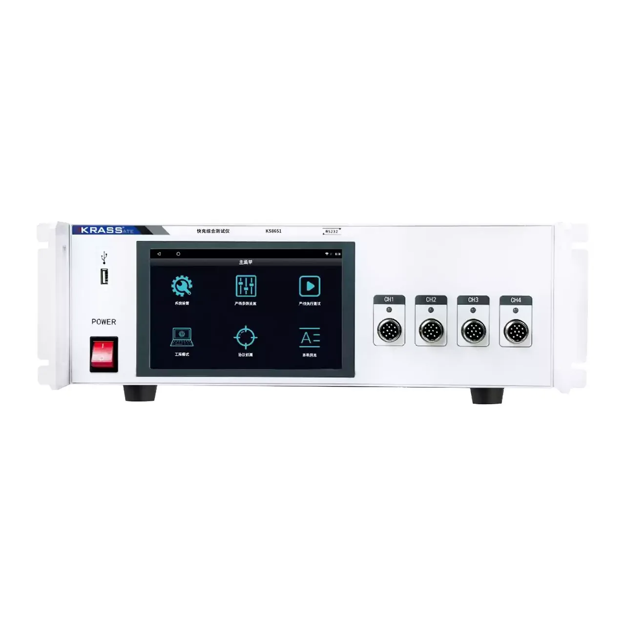
This is a single-model bench instrument with ten output ports across four modules. It is built for power banks, adapters and storage supplies, at the stage where the assembly is complete enough to deliver power but not yet packed.
The tester and its touchscreen are two parts of one system: the screen is the operating surface, and the body carries the load, the switching and the port connectors. The rear panel groups the signal, serial, network, antenna and fan positions, with a grounding terminal and the AC inlet beside them, so the cabling stays at the back while the operator works at the front.
How the power bank tester works
Each port carries its own load. When a product is connected, the instrument first acts as a sink and negotiates the charging protocol the product advertises, then closes the load in constant-current or constant-voltage mode and samples voltage and current at the port. Power is derived from the pair rather than measured separately.
That order matters. A power bank that reads correctly at no load can still fall out of regulation as soon as current is drawn, and a port that advertises a profile under no load may not hold it under a real one. Loading first and reading afterwards is the only way to see either.
Two mechanical details are handled in the test rather than by the operator. A CC lead can be inserted either way round and the instrument checks both, which removes a step that is easy to skip when a line is running. The D+ and D− lines are also checked in both orientations, which catches a cable assembled with the data pair reversed, a fault that would otherwise show up only as a product that charges slowly.
How to select the right power bank tester
The first question is port count and layout. Ten ports suit a product with several outputs, or a bench that runs several units at once; a product with fewer ports does not need the extra capacity and will not use it.
The second is current per port. The load has to hold the highest current the product can deliver with enough headroom for the protection test, and the total across ports has to stay within what the unit can dissipate, since every port that is loaded at the same time adds heat.
The third is the protocol set. The standard list covers QC2.0, QC3.0, PD2.0, PD3.0 and PD3.1; AFC, FCP, SCP and SSCP are options and have to be declared at the order stage.
The fourth is how the results are recorded: export to a USB device for a bench that archives per-unit runs, or a connection to a line system through the serial, network or wireless interface. Send the port count, the current per port and the protocol list, and a configuration can be proposed against them.
Measurement limitations and selection considerations
The voltage range is the boundary that decides the application. At 20 V, this instrument covers products that output at battery-level voltages; a charger asked to deliver a higher voltage needs a different tester, and no option on this unit extends the range.
Current accuracy and voltage accuracy are quoted in the same form, with the second term expressed against full scale rather than against reading. That means the accuracy near the bottom of the range is set by the range, not by the reading, so a low-current test on a high-current port is the least favourable case and should be planned accordingly.
Everything is measured at the port, so the lead and the connector are inside the measurement. Remote sensing is provided to compensate for the lead drop, but it compensates for the cable, not for a poor contact inside the connector, which can add a resistance that changes with temperature. A fixture that has been used for a long time should be checked against a known load before its readings are trusted.
Every value below is taken from source documentation. Where a parameter is not stated in the available material it is marked as information required rather than estimated.