Electrical Test & Measurement · Electrical Test Equipment

Programmable AC Power Source

Programmable AC source from 350 VA to 10 kVA, with 45 to 400 Hz output, two voltage ranges, 2% distortion and RS-232 control for bench and line testing.

YP4035 (7 models) ·

Key specifications

Capacity
350 VA to 10 kVA across seven models
Output voltage
1.0 to 150.0 V on the low range, 150.1 to 300.0 V on the high range
Frequency
45 to 400 Hz, 0.1 Hz steps, with 50, 60 and 400 Hz shortcut keys
Distortion
2% total harmonic distortion or less
Regulation
Voltage stability, source effect and load effect each 1% or less
Metering
Voltage, current, power, power factor and frequency on a 5 in touchscreen
Preset
Output voltage, frequency and current limit set before the output is enabled
Protection
Output cut and audible alarm when leakage current exceeds the set value
Control
RS-232 as standard; RS-485 and a signal output to order
Mains
Single phase 220 V up to 10 kVA; three phase 380 V for larger frames

A product designed for one country’s mains is often tested in another. That is the case for a programmable AC source: it is not there to supply power, it is there to supply a particular power, at the voltage and frequency the product expects to meet in service.

Product overview

Seven capacities share one control layout and one front panel. The bench frames run from 350 VA to 3 kVA; the 5 kVA and 10 kVA units are cabinets with the same panel on a larger chassis. Voltage and frequency are set on the touchscreen, with a column of function keys beside it, a rotary knob for continuous adjustment and a universal socket at the right.

The screen shows voltage, current, power, power factor and frequency together. That grouping is deliberate: a product with a failing power factor shows it here, next to the watts, without a second meter and a second set of leads.

The rear carries the RS-232 socket as standard, an RS-485 socket when ordered, the cooling fan, a second output outlet and the mains inlet.

How the programmable AC source works

The incoming mains is rectified to a direct rail and inverted back to alternating current at the frequency set on the panel. The amplitude is set separately, so voltage and frequency move independently — which is what allows a 60 Hz product to be run at 50 Hz, or a 400 Hz avionics item to be run at all.

The output is filtered to a sine wave and fed back to the control loop, which corrects for changes in the load. Two voltage ranges are provided rather than one wide range, because a single range that reaches 300 V cannot resolve a 5 V adjustment finely; switching ranges keeps the resolution usable at the low end.

Current is limited and leakage is watched. If the leakage exceeds the set value the output is switched off, the buzzer sounds and the output lamp flashes. On a line where products are powered for the first time, that behaviour stops a fault from becoming a fire.

How to select the right source

Start with the current at the test voltage, not with the wattage. A product rated at 500 W may draw 5 A at 100 V or 2 A at 240 V, and the source has to be chosen for the worse of the two cases. Motors and products with large input capacitors draw a surge well above their running current, and that surge decides the frame size more often than the steady figure.

Then the frequency band. A product for a 50 or 60 Hz market needs only the ends of the band; a 400 Hz item needs the top, and an aircraft or a machine tool may need both. The band is the same across the range, so this decides whether the instrument is suitable at all rather than which model.

Decide the frame from the environment as much as the load. A bench case fits under a shelf and can be moved; a 5 kVA or 10 kVA cabinet needs floor space, a three phase feed and a way to get it through the door.

Finally, decide how the source will be driven. Manual setting is fine for a repair bench; a test script needs RS-232 or RS-485, and that should be specified at the order. Send the voltage, the current including surge, the frequency range, the load type and the site supply.

Measurement limitations and selection considerations

The voltage ranges are fixed at the 150 V boundary. A product that needs 155 V is on the high range, where the resolution is coarser, and that is a consequence of the range split rather than of the instrument’s accuracy.

Distortion is quoted for the source, not for the combination of source and load. A load that draws a sharply peaked current will distort the voltage at its own terminals even when the source is behaving, and the longer the lead between them, the worse it gets.

The current and power readings are the source’s own measurements, taken at its output. They include the current drawn by the leads and any filter fitted between the source and the product, so a small load on a long lead can show a reading that is larger than the product’s own consumption.

Finally, an AC source is not a battery simulator and not a DC supply. It cannot reproduce the sag of a real supply during a surge, and it cannot hold a direct voltage. Where the test is about how a product behaves on a weak mains, a source with programmable output impedance is the instrument to look for, and this one is not that.

Features

  • Two continuously adjustable voltage ranges, so a 110 V product and a 230 V product are tested on the same instrument without a transformer
  • Frequency adjustable from 45 to 400 Hz in 0.1 Hz steps, for 50 Hz, 60 Hz and 400 Hz equipment on one bench
  • Distortion held at 2% or less, which keeps a product's own current waveform readable rather than hiding it behind a distorted supply
  • Voltage, current, power and power factor read at the same time, so a product's consumption can be logged without a second instrument
  • Current limit and leakage alarm both cut the output, which matters when the load is a product being brought up for the first time
  • RS-232 as standard and RS-485 to order, so the source can be driven from a test script rather than by hand
  • Seven capacities from 350 VA to 10 kVA on the same control layout, so a test written on one frame runs on another

Technical specifications

Every value below is taken from source documentation. Where a parameter is not stated in the available material it is marked as information required rather than estimated.
Output
Capacity350 VA, 500 VA, 1 kVA, 2 kVA, 3 kVA, 5 kVA and 10 kVA by modelStandard
Low range1.0 to 150.0 V, continuously adjustableStandard
High range150.1 to 300.0 V, continuously adjustableStandard
Frequency45 to 400 Hz, 0.1 Hz per stepStandard
Shortcut keys50 Hz, 60 Hz and 400 Hz, selected from the panelStandard
WaveformSine waveStandard
Crest factor1.41 ±0.10 in the common table; 3:1 on the 350 VA sheetInformation required
Maximum current at 120 V4.2 A on 500 VA, 8.4 A on 1 kVA, 16.66 A on 2 kVA, 25 A on 3 kVA, 41.66 A on 5 kVA, 83.33 A on 10 kVAStandard
Maximum current at 240 V2.1 A on 500 VA, 4.2 A on 1 kVA, 8.3 A on 2 kVA, 12.5 A on 3 kVA, 20.83 A on 5 kVA, 41.66 A on 10 kVAStandard
Performance
Frequency stability0.1% or less in the common table; 0.01% or less on the 350 VA sheetInformation required
Voltage stability1% or lessStandard
Total harmonic distortion2% or lessStandard
Source effect1% or lessStandard
Load effect1% or lessStandard
Efficiency90% or more, and 80% or more at 3 kVA and belowStandard
Metering and control
Display5 in full touchscreen, with voltage and frequency shortcut indicators beside itStandard
Voltage display1% of reading plus 0.1% of range, resolution 0.1 VStandard
Current display1% of reading plus 0.1% of range, resolution 0.001 A or 0.1 AStandard
Power display1% of reading plus 0.1% of range, resolution 0.01 W or 0.1 kWStandard
Power factor display±0.1, resolution 0.01Standard
Frequency display0.1% of reading, resolution 0.1 HzStandard
PresetOutput voltage, output frequency and output current limitStandard
Leakage alarmOutput switched off with a buzzer and a flashing output lamp when leakage exceeds the set valueStandard
Electrical and mechanical
Input, 10 kVA and belowSingle phase 220 V ±10%, 50 Hz ±5 HzStandard
Input, above 10 kVAThree phase 380 V ±10%, three phase four wire plus earth, 50 Hz ±5 HzStandard
CaseBench case with a 430 mm square footprint; 5 kVA and 10 kVA supplied as cabinetsStandard
Height155 mm in the dimension drawing; 168 mm including feet on the 1 kVA model cardInformation required
Weight18 kgStandard
Output socketUniversal socket on the front panel; a second outlet on the rearStandard
Supplied accessoriesNot listed in the materialInformation required

Available models

Selection table
Model Configuration Key ranges Availability
YP4035 350 VA, bench case 1.0 to 300.0 V in two ranges; 3 A low range, 1.5 A high range; 45 to 400 Hz Smallest capacity
YP4050 500 VA, bench case 1.0 to 300.0 V; 4.2 A at 120 V, 2.1 A at 240 V Entry model for small products
YP4101 1 kVA, bench case 1.0 to 300.0 V; 8.4 A at 120 V, 4.2 A at 240 V Common bench size
YP4102 2 kVA, bench case 1.0 to 300.0 V; 16.66 A at 120 V, 8.3 A at 240 V For larger single loads
YP4103 3 kVA, bench case 1.0 to 300.0 V; 25 A at 120 V, 12.5 A at 240 V Largest bench case
YP4105 5 kVA, cabinet 1.0 to 300.0 V; 41.66 A at 120 V, 20.83 A at 240 V Cabinet frame
YP4110 10 kVA, cabinet 0 to 300 V on the model card; 83.33 A at 120 V, 41.66 A at 240 V Largest capacity, cabinet frame

Customization

  • RS-485 communication in place of, or in addition to, RS-232
  • Signal output interface
  • Cabinet frame for the 5 kVA and 10 kVA capacities

Certification and compliance

Certification documents not yet supplied

Certifications are only published once a certificate copy can be produced, so this section is deliberately empty rather than populated with assumed approvals. Tell us which approvals your application requires and we will confirm what is available for this instrument.

Parameters still to be confirmed

The following are required for a complete specification but are not stated in the documentation supplied to us. They are listed rather than estimated:

  • Frequency stability, given as 0.1% or less in the common table and 0.01% or less on the 350 VA sheet
  • Crest factor, given as 1.41 ±0.10 and as 3:1
  • Output voltage range for the 500 VA and 5 kVA models, whose cards show both 1 to 300 V and 1 to 500 V
  • Case height, 155 mm in the drawing and 168 mm including feet on the 1 kVA card
  • Output voltage range of the 1 kVA model, which its card does not print
  • Whether the 10 kVA model starts at 0 V or at 1 V, as its card and the common table differ
  • Maximum current of the 350 VA model at 120 V and 240 V, which the comparison table gives only as range and current pairs
  • Supplied accessories, since no packing list was provided
  • Calibration certificate availability
  • Warranty period and terms

Frequently asked questions

Can one source test both 50 Hz and 60 Hz products?

Yes. The frequency is adjustable across the whole band with 50, 60 and 400 Hz available as shortcut keys, so a product built for one market can be run at the frequency of another. That is the point of the instrument for an exporter: the same unit stands in for the supply of the destination country rather than the supply in the workshop.

What decides the capacity, the watts or the amps?

The amps, at the voltage the product will run at. A product that draws 6 A at 120 V needs a source whose low-range current rating exceeds 6 A, which puts it at the 1 kVA model rather than the 500 VA one, even though the wattage looks modest. A load with a poor power factor draws more current for the same wattage, so the current rating is the figure to compare.

What has to be confirmed before a quotation?

The highest voltage and the highest current the test needs, the frequency range, whether the load is a resistive bench item or a motor with a starting surge, whether the source will be driven from a PC, and the mains supply available at the site, since the larger frames need a three phase feed.

Related products

Other models in the same range

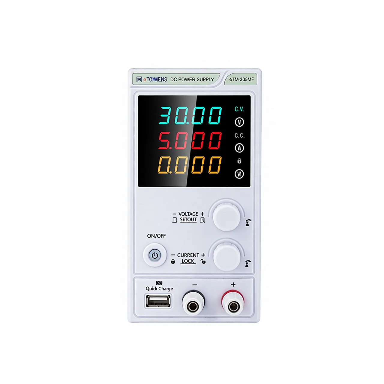
Narrow benchtop power supply seen from the front, with a large LED display reading 30.00 volts, 5.000 amps and 0.000 watts, two adjustment knobs, an ON/OFF key, a quick-charge USB socket and one red and one black output terminal

eTM-152MF (5 models) · Electrical Test Equipment

Miniature Adjustable DC Power Supply

Bench DC power supply in a narrow 80 mm case, with 15 to 150 V and 2 to 20 A models, four-digit voltage, current and power readout, and preset without shorting the output.

Output voltage
15, 30, 60, 100 or 150 V maximum, by model
Output current
2 to 20 A maximum, by model
Readout
Four-digit LED for voltage, current and power at the same time
Setting resolution
10 mV below 100 V, 0.1 V at 100 V and above
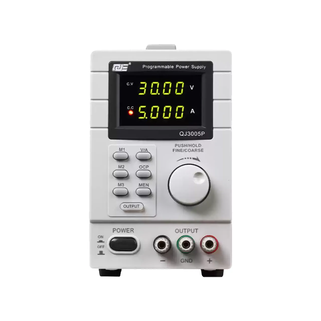
Upright bench power supply seen from the front, with a dark display reading 30.00 volts and 5.000 amps, a CV lamp lit, six small keys including M1 to M3, a large rotary knob and three output posts at the bottom

QJ300N (4 models) · Electrical Test Equipment

Adjustable Linear DC Power Supply

Linear bench supply, 30 V at 3 or 5 A, with 1 mVrms ripple, fine and coarse adjustment on one knob, three stored settings and an option for USB control.

Output voltage
0 to 30 V, continuously adjustable
Output current
0 to 3 A or 0 to 5 A, by model
Setting accuracy
0.5% + 20 mV on voltage, 0.1% + 5 mA on current, at 25 ±5 °C
Ripple
1 mVrms on voltage and 3 mArms on current, measured from 20 Hz to 20 MHz
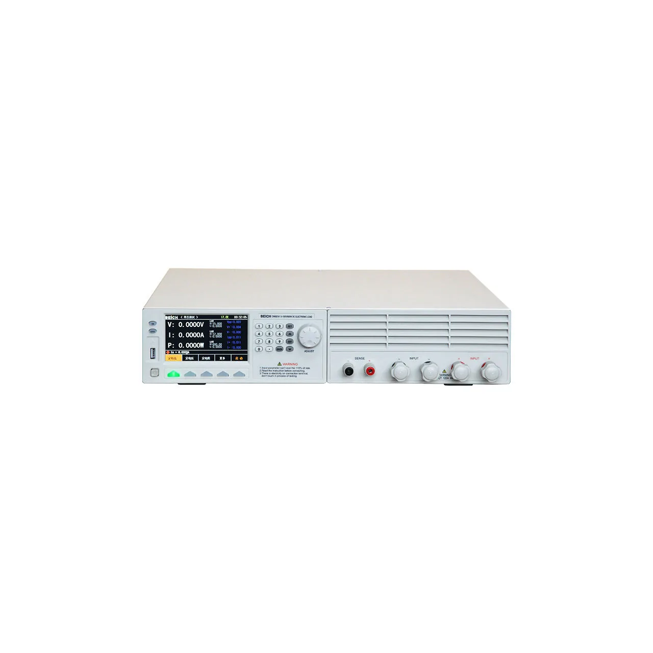
Off-white benchtop load seen from the front, with a colour screen at the left showing voltage, current and power readings, a numeric keypad and adjustment knob beside it, ventilation slots across the right-hand half and two pairs of input terminals with sense terminals along the bottom right

CH6321A (5 models) · Electrical Test Equipment

Programmable DC Electronic Load

Programmable DC electronic load with 150 V and 500 V inputs, 60 to 240 A, 600 to 1500 W, six load modes and battery, dynamic and OCP test functions.

Input voltage
0 to 150 V on four models; 0 to 500 V on four models
Input current
0.1 mA to 60 A, 120 A or 240 A depending on model
Input power
600 W, 900 W, 1200 W or 1500 W depending on model
Load modes
Constant voltage, constant current, constant power, constant resistance, short circuit and open circuit

Request a quotation for the YP4035

Send the configuration you need and we will confirm availability, lead time and terms. Minimum order quantity is 1 pc.

Request for quotation

Request a quotation - YP4035

Send the technical detail and we will confirm availability, lead time and terms. In-stock items ship within 48 hours; customized specifications typically take 2-10 days. Minimum order quantity is 1 pc.

The more of this you can give us, the fewer exchanges are needed before we can quote.
No file chosen
Datasheet, drawing, BOM or photograph. One file, up to 10 MB (PDF, Office, image or ZIP).

By submitting this form you agree that we may contact you about this enquiry. We do not sell or share enquiry data. See our privacy policy.

Items held in stock are dispatched within 48 hours of order confirmation. Customized specifications are produced to order and typically ship within 2 to 10 days. Transit time then depends on the shipping method and destination.

Request a Quote WhatsApp