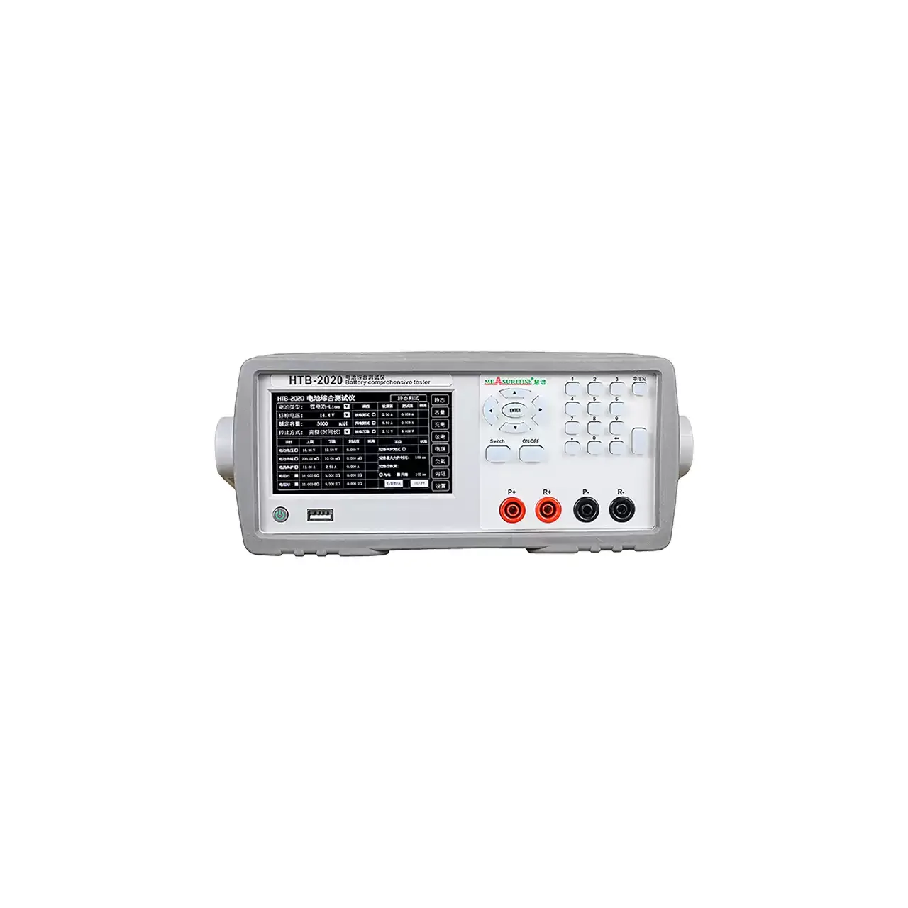
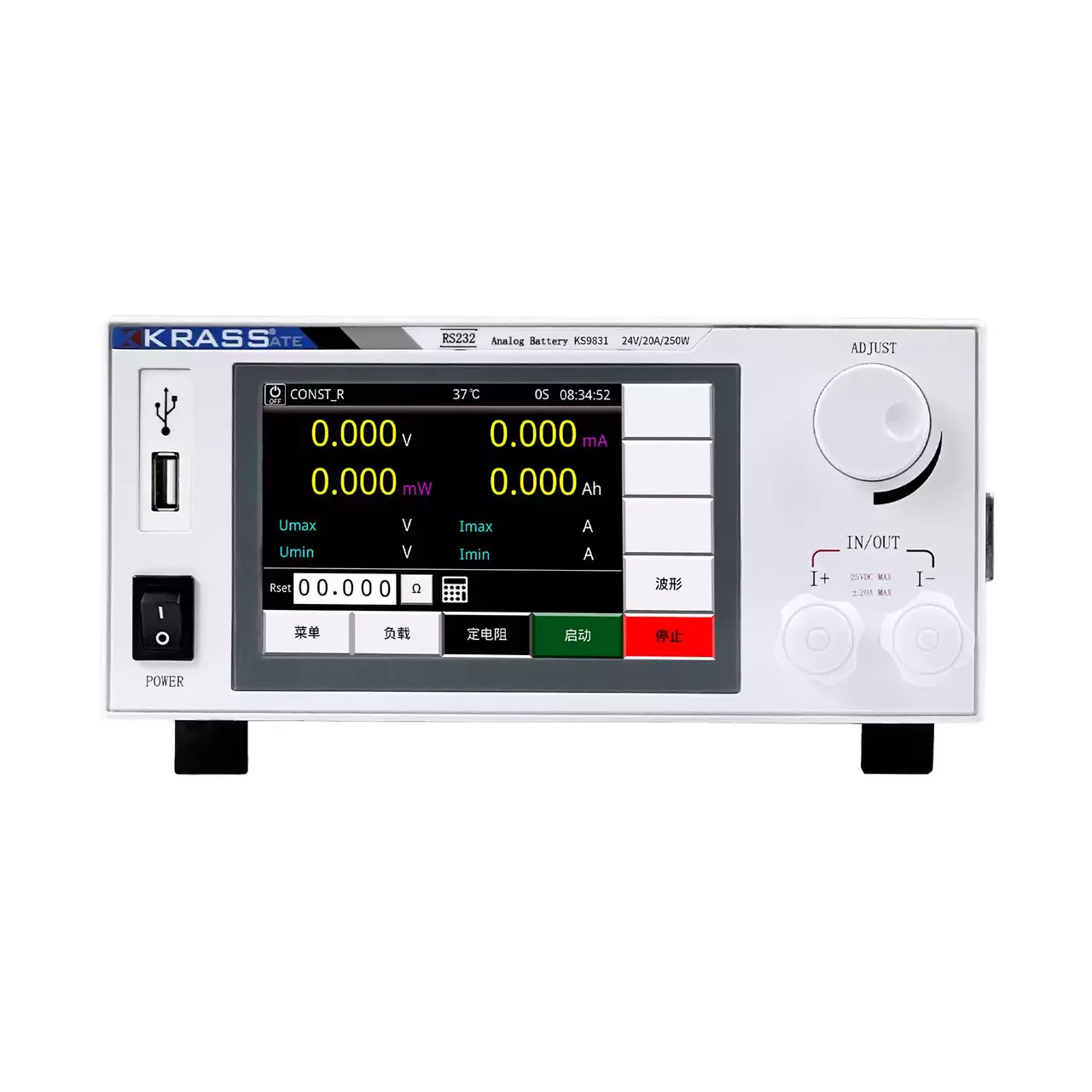
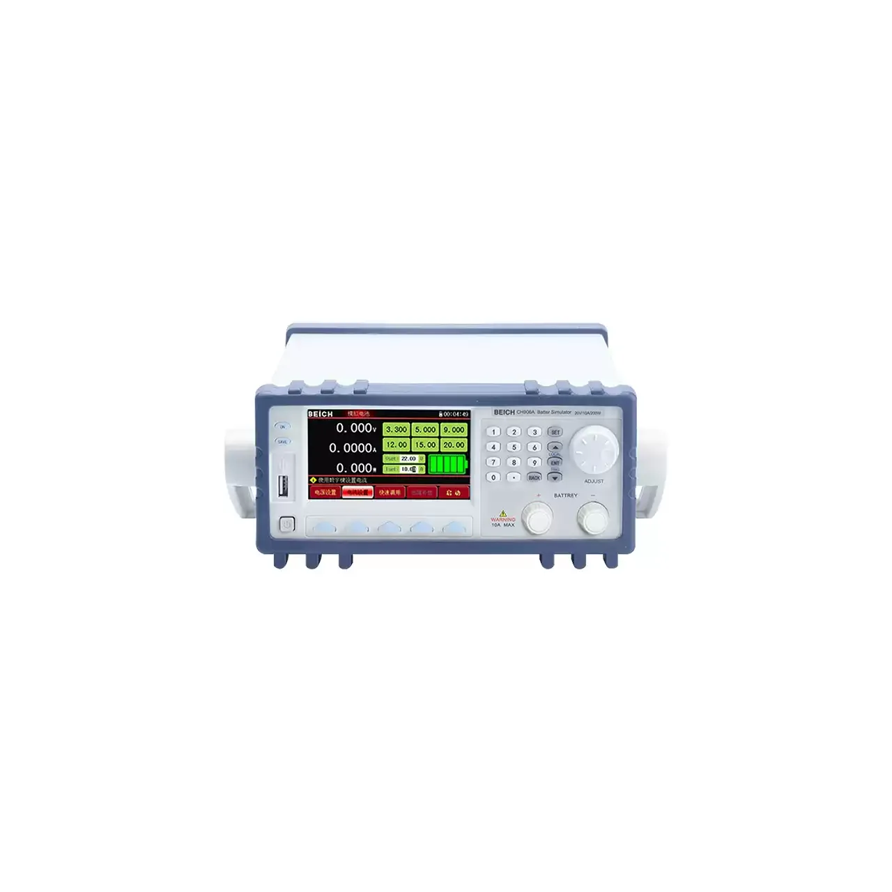
- Measurement
- AC internal resistance and DC terminal voltage, shown together
- Test method
- Four-terminal measurement with a 1 kHz alternating current
- Resistance range
- 3 mΩ to 3 kΩ on most models; 0.1 µΩ to 3.1 kΩ on the high-voltage models
- Voltage range
- 60 V, 300 V, 600 V, 1000 V or 1500 V DC, depending on model
- Resistance accuracy
- ±0.3% or ±0.5% of reading, depending on model
- Voltage accuracy
- ±0.01% on one family; 0.05% on the other
- Resolution
- 0.1 µΩ and 10 µV at the bottom of the range
- Sorting
- 10 bins on one family; six levels on the other, resistance and voltage judged independently
- Speed
- Up to 100 readings per second on one family; 70 on the other
- Display
- 4.3-inch colour LCD
A cell that reads the right voltage can still be the wrong cell. What separates a good cell from a marginal one, at the same state of charge, is usually its internal resistance, and that is a milliohm quantity that has to be measured with the cell in place and without loading it.
Product overview
These are bench and line instruments, not chargers. Each one drives a 1 kHz alternating current through the cell on one pair of terminals, senses the resulting voltage on a second pair, and reports the internal resistance and the terminal voltage at the same time on a 4.3-inch colour display.
Two ranges of instrument are covered here. The first runs from 60 V to 1500 V input classes, with seven resistance ranges and a bottom end of 0.1 µΩ on the high-voltage models. The second is a two-model family, 60 V and 200 V, with six resistance ranges from 30 mΩ to 3000 Ω and a lower test current. Both fit the same job on a line; they differ in how much voltage they can sit on and how finely they divide the low end.
How the battery internal resistance tester works
The instrument applies a small alternating current at 1 kHz through the cell, using the drive pair of the four-terminal connection. The sense pair picks up the alternating voltage across the cell. Because the sense pair carries almost no current, the resistance of the leads, the clips and the contact to the cell does not appear in that voltage, and the ratio of voltage to current is the cell impedance at that frequency.
An alternating current is used rather than a direct one because a direct current would polarise the cell. The cell would push back with its own EMF and the reading would drift for as long as the current was applied. At 1 kHz the measurement sits above the charge-transfer region and below the inductive region, so the number is stable, repeatable and dominated by the electrolyte and the current path.
The terminal voltage is measured on the same sense pair, which is why the two readings belong to the same instant. That matters on a line: a cell that is being charged or has just come off a formation step will move in voltage, and a resistance measured at one moment compared against a voltage measured at another is not a valid pair.
Sorting compares each of the two readings against its own limits. A cell is only passed when both are inside, so a cell with a good resistance but a low voltage, or the reverse, is separated out rather than averaged into a pass.
How to select the right battery internal resistance tester
Start with the highest voltage the fixture will ever see. A single cell or a small pack sits inside the 60 V class; a module of cells in series needs the 300 V or 600 V class; a full string needs 1000 V or 1500 V. Leave margin above the nominal pack voltage, because a fully charged string is above its nameplate figure.
Then the bottom of the resistance window. If the smallest cell to be graded is a small pouch or a coin cell, the 3 mΩ range with 0.1 µΩ resolution is the requirement, and on one family that resolution only comes with the high-voltage models. If every cell is a large prismatic or a lead-acid block, the 30 mΩ range is enough and the short-range model is the cheaper fit.
Then the accuracy the customer’s drawing calls for. The two families differ by a factor of about two on resistance and five on voltage; where the pass window is wide, neither difference matters, and where it is narrow, the better figure is the reason to choose.
Then the interface. A bench that reads the display needs nothing more. A line that sorts needs the handler or external I/O port, and a line that logs needs the serial link or the USB host socket. Where the cell data has to reach a PLC, the protocol matters, and both families state SCPI and Modbus RTU.
Finally, the fixture and the leads. The Kelvin clip, the pin probe and the bar probe are not interchangeable on a small terminal, and the lead length affects the highest resistance range more than the lowest.
Measurement limitations and selection considerations
The reading is an impedance at 1 kHz, not a direct-current resistance. A cell with a high charge-transfer resistance can look acceptable at 1 kHz and poor under a load step. Where the application is a high-rate discharge, the direct-current figure is the one to ask for, and it comes from a load test rather than from this instrument.
The test current is deliberately small, below 10 mA on one family, with an open-circuit voltage below 20 mV. That is what makes the measurement non-destructive, and it is also why the instrument cannot substitute for a capacity or a load test. It grades a cell, it does not characterise it.
Contact quality sets the floor of the measurement. At 0.1 µΩ a clip that is not fully seated reads as a resistance increase, which is why the contact check exists and why it should be enabled rather than bypassed for speed. Probe pressure and tip condition matter more than the instrument’s accuracy figure at that level.
Temperature moves the reading. Both families offer temperature compensation, but compensation is a calculation against a reference temperature, not a removal of the effect; a cell measured cold and a cell measured warm will still differ if the compensation coefficient is wrong for that chemistry.
Voltage class is a safety boundary as much as a range. A 60 V instrument connected to a 400 V string is outside its rating, and the isolations and clearances inside a 1500 V model are not the same as those in a 60 V one. The class should be chosen for the highest voltage that can be present, not for the voltage usually present.
Every value below is taken from source documentation. Where a parameter is not stated in the available material it is marked as information required rather than estimated.