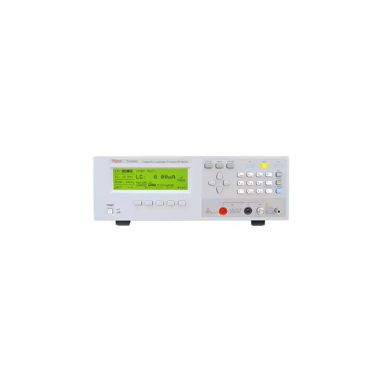
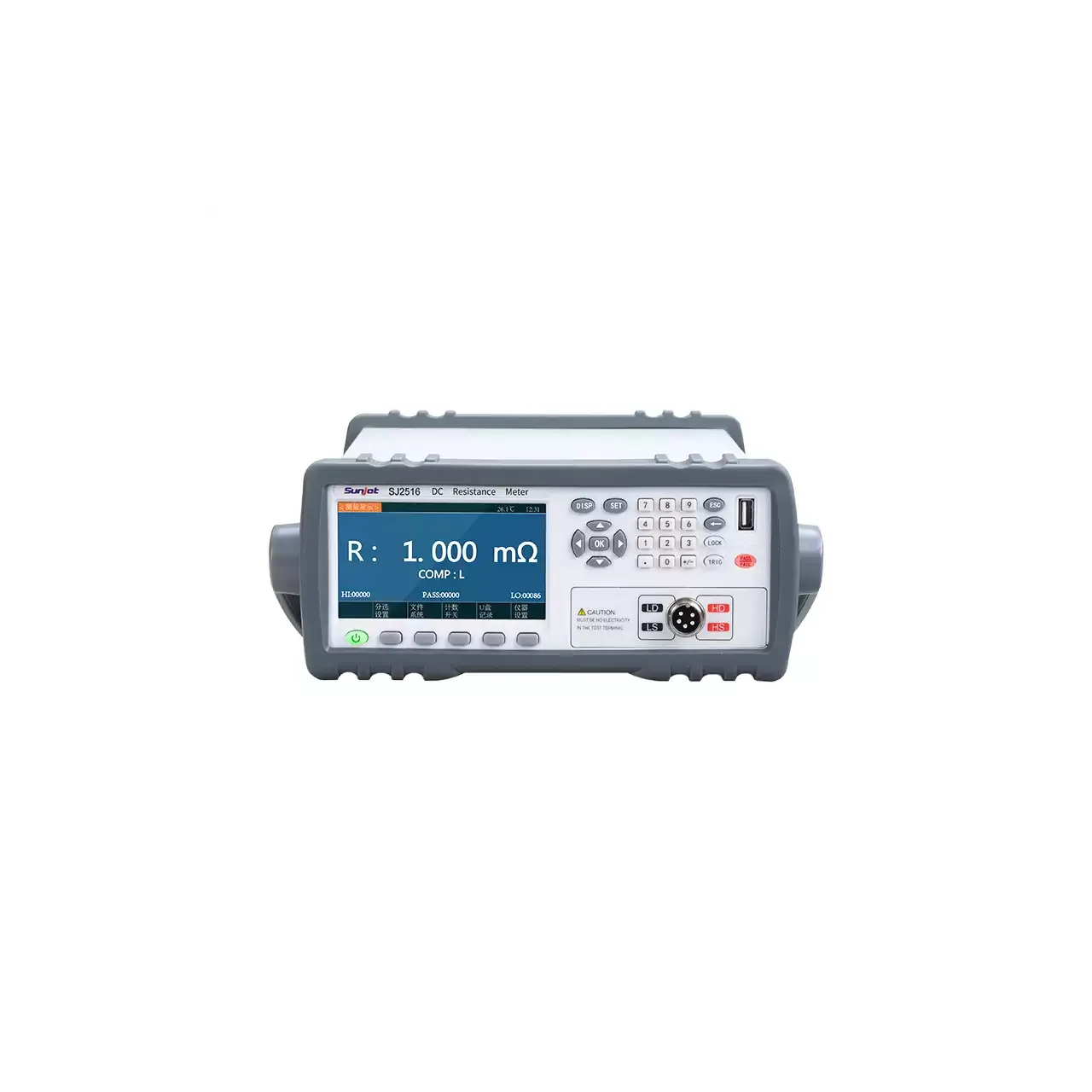
A diode fails in two different ways, and a single forward-voltage check catches only one of them. A part can conduct correctly in the forward direction and still leak badly in reverse, which is the failure that shows up later as a hot component or a dead rectifier. This instrument measures both directions, and does it fast enough to sit on a sorting line.
Product overview
The HG2600 is a benchtop diode tester for forward and reverse measurement. It forces a constant current through the diode and reads the forward voltage, then applies a reverse voltage and reads the leakage current. Four quantities are reported: reverse voltage Vka, reverse leakage Ika, forward current Iak and forward voltage Vak.
The reverse side reaches 1200 V across two ranges split at 135 V, and the leakage range extends to 2200 µA with a resolution of 0.01 µA on the examples in the source. The forward side covers 0.1 to 2.5 V.
The front panel has the display at the left with the four readings stacked, soft keys beside it, a direction pad and numeric keypad at the right, and the two test sockets along the lower edge. The body is 360 mm wide and about 5 kg.
How the diode tester works
In the forward direction the instrument acts as a current source. It forces a set current through the junction and measures the voltage that appears across it. Because the current is forced rather than the voltage, the reading is the forward characteristic at a defined operating point, which is what a datasheet specifies.
In the reverse direction the roles change. The instrument applies a set voltage and measures the current that flows, which for a good diode is very small. That is why the leakage range is expressed in microamps and why the resolution matters more than the full-scale figure: the difference between a good part and a marginal one is often a fraction of a microamp.
The test terminals are arranged for a four-wire Kelvin lead, so the resistance of the lead and of the fixture is kept out of the voltage measurement. The two directions can be run in sequence from one trigger, which is what makes the instrument usable on a handler rather than as a bench meter.
Three speeds are offered at 155, 190 and 260 ms per reading. The slower settings give the current source and the leakage measurement more time to settle, which matters on a part with significant junction capacitance.
How to select the right diode tester
Start with the reverse voltage the part has to block. A 1200 V range covers rectifiers and high-voltage types; a small-signal diode needs none of it, but the range does not get in the way. What matters is that the working reverse voltage falls inside a range rather than at its edge.
Then the leakage limit. This is the number that decides whether the instrument is suitable, because a limit expressed in nanoamps cannot be checked on an instrument whose resolution stops at a microamp. Compare the resolution, not the full-scale range, with the tightest limit in the drawing.
Then the forward current. The forward voltage is only meaningful at a stated current, so the instrument has to be able to force that current. The range printed in the material extends to 30 A with the separator unclear, which is worth confirming against the parts before the instrument is specified for them.
Then the interface. The PLC connector carries the result to a sorting machine; the serial link is for collecting readings on a computer and is listed as an option.
Send the diode type, the reverse voltage, the leakage limit and the forward current at which the part is specified, and a configuration can be proposed against them.
Measurement limitations and selection considerations
The instrument measures at DC. It does not describe switching behaviour, recovery time or junction capacitance, so a part that passes here can still be wrong for a fast circuit. Those are separate measurements.
Leakage readings are small and slow to settle. A diode with a large junction, or one measured immediately after a forward test, carries charge that takes time to dissipate, and a reading taken too early is higher than the true leakage. The slower speed settings exist for this reason, and a fixture that triggers the instrument the moment it closes will read high.
Temperature affects leakage strongly. A part measured cold and the same part measured warm can differ by a large factor, so the limit has to be tied to a temperature, and the bench has to hold it.
The forward current range in the material is printed with an unclear separator. Until that is confirmed, the instrument should not be specified for a part whose test current sits near the top of the range.
Finally, the reverse voltage is applied by the instrument and the leakage is read at that voltage. A part whose leakage is specified at a voltage the instrument cannot set is outside what this tester can check, whatever its range figure says.
Every value below is taken from source documentation. Where a parameter is not stated in the available material it is marked as information required rather than estimated.