- Input power
- 150 W on the three 60 V and 150 V models; 300 W on the largest
- Input voltage
- 0 to 60 V, or 0 to 150 V on the two higher models
- Input current
- 0.1 mA to 6 A, or 0.1 mA to 30 A on the two higher models
- Accuracy
- ±(0.05% + 0.03% FS) on voltage and current
- Resolution
- 0.1 mV and 0.01 mA on the low ranges; 1 mV and 0.1 mA on the high ranges
- Sampling
- 500 kHz synchronous; dynamic load mode at 50 kHz
- Protocols, all models
- PD2.0, PD3.0 with PPS, QC2.0, QC3.0, QC4+, PE1.1, PE2.0, BC1.2 and Apple 2.4 A
- Display and interfaces
- 4.3-inch TFT colour display; isolated RS232C, USB host and SCPI
- Body
- 215 × 88 × 350 mm
A fast-charge charger is two products in one: a power supply that has to hold a voltage under load, and a negotiation partner that has to agree a protocol before it will deliver anything. Testing it needs both halves at once, which is why a load alone is not enough.
Product overview
The CH97 series combines a programmable DC electronic load with fast-charge protocol detection in one benchtop instrument. The load draws current from the charger and measures voltage, current and power; the protocol section asks the charger what it can deliver and sets up the negotiation, so the load can be applied at the voltage the product actually uses.
Four models cover the range. Two are 150 W units at 0 to 60 V, one is 150 W at 0 to 150 V, and the largest is 300 W at 0 to 150 V. Protocol support steps up across the series, from PD2.0, PD3.0 with PPS, QC and Apple modes on the entry model, to PD3.1 on the largest.
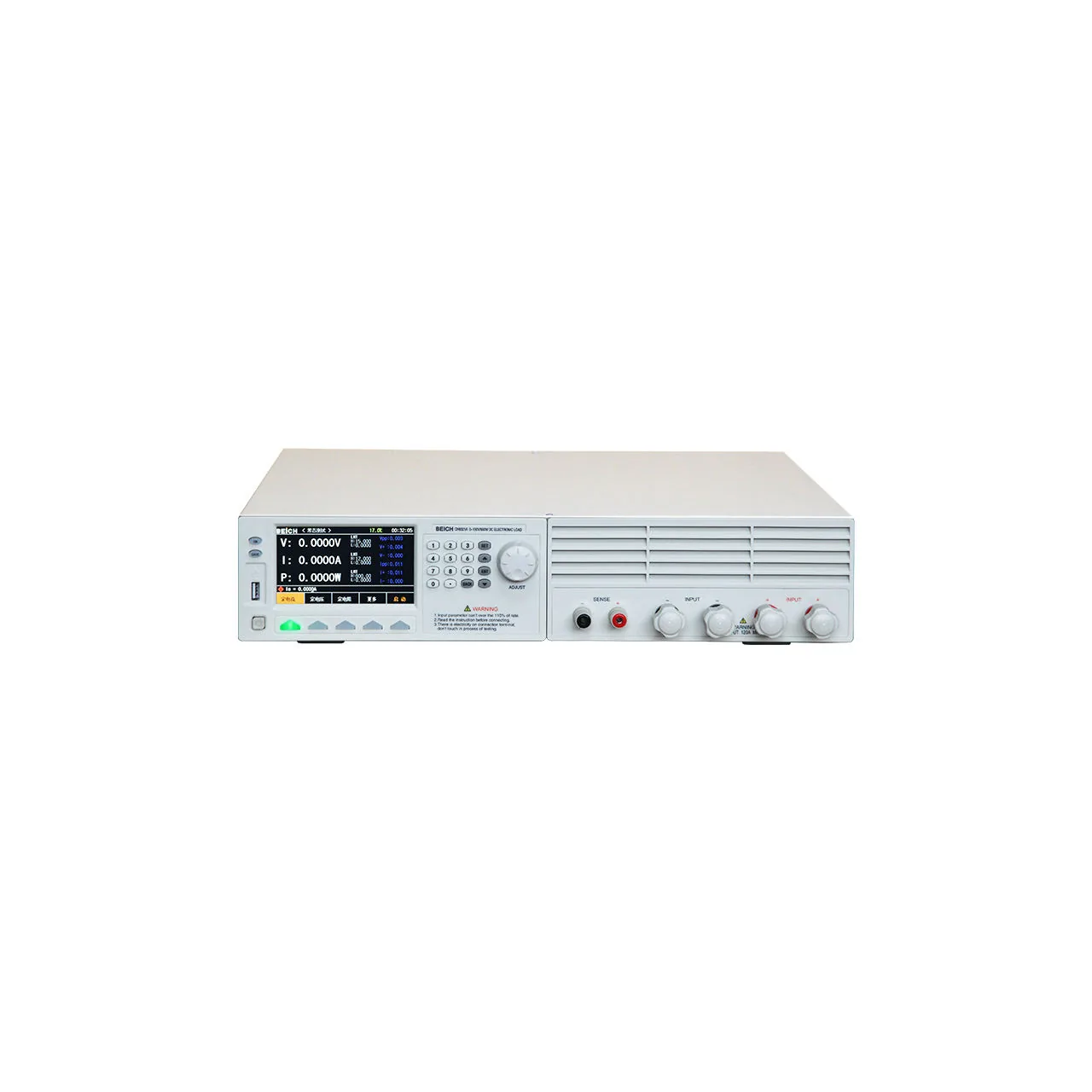
The front panel carries a 4.3-inch colour display at the left, with the readings and the protocol panel side by side, a numeric keypad and a rotary knob at the right, and the load terminals along the lower edge. The rear carries the sense and control terminals, the serial port and the mains inlet.
How the fast-charge load works
The load is a programmable current sink connected across the output of the device under test. Setting a current forces the charger to deliver it, and the voltage that appears at the terminals is the charger’s regulation at that point. Voltage and current are sampled at 500 kHz, which is fast enough to see the ripple on the output rather than an averaged value.
The protocol section works on the other side of the interface. It drives the CC and data lines to ask the charger which standard it supports, reads the answer, and then requests a voltage and current from that standard’s menu. Because the request is a negotiation rather than a fixed setting, the instrument has to identify the protocol before the load can be applied at the intended operating point.
The two cable tests follow from the same interface. A USB-C cable can be inserted either way round, so CC1 and CC2 are detected and flipped automatically. On the higher models D+ and D- are tested on both sides as well, and an E-marker is built in so a 5 A cable can be checked in both orientations.
Ripple is measured as a peak-to-peak figure with the positive and negative peaks reported separately, which distinguishes a charger with a steady output from one that rings on load changes. The 50 kHz dynamic mode does the same job for a load that steps rather than holds.
How to select the right fast-charge load
Start with the protocol list, not with the wattage. The protocols are fixed by the model, so a product that uses PD3.1 needs the largest model whatever its power rating, and a product that uses VOOC needs one of the two 150 V models. Making the power rating the first question leads to a model that cannot negotiate with the product at all.
Then the voltage and current. A 60 V model covers chargers up to 60 V; a 150 V model covers the higher-voltage adapters and the 30 A current range comes with it. Check the maximum current the product delivers against the range rather than the wattage alone, because a 100 W charger at 20 V draws 5 A and one at 5 V draws 20 A.
Then the measurements. Ripple is not on every model, and it is the measurement that separates a charger that works from one that works quietly. OCP and maximum power point capture are on the series; the list test turns a sequence of operating points into a single pass or fail.
Finally the bench. The isolated serial link with SCPI and the USB host port are for a bench that runs the test from a computer and keeps the records; the GO and NG outputs and the external start input are for a fixture that does the same thing in hardware.
Send the protocol list, the maximum voltage and current, and the measurements the drawing requires, and a model can be proposed against them.
Measurement limitations and selection considerations
The load is a sink. It draws current from the device under test and cannot source it, so a product that needs to be charged and discharged at the same time needs two instruments rather than one.
Protocol detection answers what the charger advertises, not whether it performs. A charger can negotiate a 20 V profile and then fail to hold it under load; that is what the load is for. The two results have to be read together, and a page that reports only the protocol result is reporting half the test.
Cable tests are limited by the cable in use. A two-wire cable will pass the CC orientation test on either side because there is nothing to detect; the test is meaningful on a cable with an E-marker or with the data lines present.
Ripple figures depend on the bandwidth of the measurement. The instrument samples at 500 kHz, but the figure it reports depends on the filter setting, so two instruments with different settings will report different ripple on the same charger. The setting has to be part of the test record.
Finally, the two statements in the material about ripple availability do not agree for the middle model. Until that is settled, a bench that needs ripple should be specified on a model where the material is unambiguous.
Every value below is taken from source documentation. Where a parameter is not stated in the available material it is marked as information required rather than estimated.