- Input voltage
- 0 to 120 V on three models; 0 to 360 V on the other three
- Input current
- 1 mA to 60 A on all six, as printed in the parameter table
- Input power
- 600 W, 900 W or 1200 W, one of each in both voltage classes
- Load modes
- Constant voltage, constant current, constant power, constant resistance, short circuit and open circuit
- Voltage accuracy
- ±(0.1% + 0.03% FS) on every voltage range
- Current accuracy
- ±(0.1% + 0.05% FS) from 0 to 6 A; ±(0.2% + 0.05% FS) from 6 to 60 A
- Resolution
- 1 mV and 1 mA on the lowest ranges; display resolution 0.0001
- Battery test
- 2 to 120 V or 360 V, capacity to 9999 AH, with internal resistance and a discharge curve
- Body
- 430 × 88 × 450 mm
A 1200 W load is not simply a bigger version of a 150 W one. At sixty amps the leads become part of the circuit, the sense point decides the reading, and the difference between a supply that works and one that trips is often the load’s own protection envelope. This series is built for that end of the bench.
Product overview
The CH881 series is a programmable DC electronic load in six models. Three take 0 to 120 V and three take 0 to 360 V, and each voltage class is offered at 600 W, 900 W and 1200 W. All six take 1 mA to 60 A.
The load has six modes: constant voltage, constant current, constant power, constant resistance, short circuit and open circuit. A battery discharge mode with internal resistance and a plotted curve, a dynamic test with pulse widths from 1 ms to 6 s, a 60-step list test and remote sense at the rear terminals are fitted across the range.
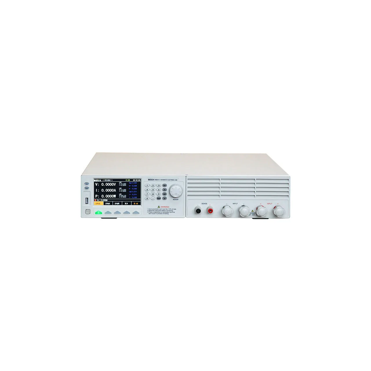
The body is 430 × 88 × 450 mm, a two-unit bench case with the display and keypad at the left, a vent grille across the right half and the sense and input terminals along the lower right. One hundred setups are held internally and five hundred more on a USB drive.
How the high power load works
The load sinks a programmed current from the source and holds it while the terminal voltage is sampled at 500 kHz. At 60 A the current is high enough that the resistance of the leads and of the connections produces a measurable drop, so the instrument provides a separate sense pair at the rear. The sense leads carry no current, which means they measure the voltage at the source rather than the voltage the load has been left with after the lead drop.
The modes change the reference the load regulates against. Constant current holds the current, constant voltage holds the voltage, constant resistance presents a fixed resistance and constant power holds the product of the two. Short circuit applies the lowest resistance the stage can present, and open circuit removes the load entirely, which is how the no-load condition of a supply is checked without disconnecting it.
The battery mode runs a controlled discharge. The load holds a current or a resistance, the pack voltage falls, and the instrument accumulates capacity until the voltage reaches the cut-off or the time limit is reached. Internal resistance is derived from the change in voltage against the change in current, and the curve is plotted as the discharge proceeds.
How to select the right high power load
Start with the power, not the current. Every model reaches 60 A, but only at low voltage: 600 W is 60 A at 10 V, 1200 W is 60 A at 20 V. A 48 V supply at 25 A asks for 1200 W, so the largest model is the only one that will hold that operating point, whichever voltage class is chosen.
Then the voltage class. A 120 V model covers adapters, chargers, 12 V and 24 V systems and most single-phase supplies; a 360 V model covers power factor corrected front ends, 48 V telecom supplies and higher-voltage rails. The 360 V class costs nothing in current, so the choice is made by the highest voltage the bench will see.
Then the measurement. Remote sense is what makes a 60 A reading meaningful, and it is fitted to every model. The battery function, the dynamic test and the list test are also across the range, so the choice between models is about range rather than about which functions are present.
Then the record. The serial link with SCPI and the USB host port are standard, with five hundred setups on a drive; the PC software is an option. A bench that changes product often benefits more from the stored setups than from the software.
Send the maximum voltage and current of the source, the power it delivers continuously, and the tests the drawing requires, and a model can be proposed against them.
Measurement limitations and selection considerations
The power rating limits the current at high voltage. A 1200 W model holds 60 A to 20 V and about 33 A at 36 V; above that the protection trips. Reading the 60 A figure as available across the range is the most common way to specify a load that cannot run the test.
The load sinks current and cannot source it. A battery that has to be charged and discharged in one cycle needs a source as well, and a bidirectional test needs a different instrument.
Remote sense corrects the DC drop, not the AC. The sense leads remove the resistive error from the voltage reading, but they do not remove the inductance of the power leads, which is what limits how fast the current can change. A dynamic test at high current is bounded by the cabling as much as by the instrument.
The battery mode derives internal resistance from a current step. On a pack with a large capacitance, or one that has just been charged, the voltage takes time to settle and the derived figure depends on when it is taken. The test conditions belong with the result.
Finally, the material gives no weight and no mains input for any of the six models, and the rear panel carries a 50 VA MAX marking that does not by itself define the supply. Both should be confirmed before the instrument is specified into a rack, where the mechanical load and the supply capacity are both fixed.
Every value below is taken from source documentation. Where a parameter is not stated in the available material it is marked as information required rather than estimated.