Electrical Test & Measurement · Electrical Test Equipment

Wide-Range Programmable DC Electronic Load

Four-model programmable DC electronic load with a 0 to 360 V input, 150 W or 300 W, five load modes, battery discharge testing and 500 kHz ripple measurement.

CH9720B (4 models) ·

Key specifications

Input voltage
0 to 360 V on all four models
Input current
1 mA to 30 A as printed in the parameter table; 0.1 mA on the model cards
Input power
150 W on CH9720B and CH9720BU; 300 W on CH9720C and CH9720CU
Load modes
Constant voltage, constant current, constant power, constant resistance and short circuit
Accuracy and resolution
±(0.05% + 0.03% FS) on voltage and ±(0.05% + 0.05% FS) on current; 0.1 mV and 0.1 mA on the lowest ranges
Sampling
500 kHz, with voltage and current ripple measured as Vpp and Ipp
Battery test
0.8 to 360 V, capacity to 999 AH, discharge time 1 to 60000 s
Interfaces
RS232C with SCPI, handler connector and USB host
Body
230 × 100 × 350 mm, about 6 kg or 6.5 kg

A bench supply is judged by what happens when it is asked for current it did not plan to give. An electronic load is the instrument that asks. This series puts a 360 V, 30 A sink in a body the size of a bench meter, in two power levels and with or without local storage.

Product overview

The CH9720X series is a programmable DC electronic load in four models. All four take 0 to 360 V and up to 30 A; two deliver 150 W and two deliver 300 W. The models with a U suffix add USB storage and screen capture, so readings and screen images can be saved without a computer.

The load has five modes: constant voltage, constant current, constant power, constant resistance and short circuit. A battery discharge function, a dynamic test with two timing values, ripple measurement and a 60-step list test sit alongside them. The instrument samples at 500 kHz and displays voltage, current and power against their limits on a 4.3-inch colour screen.

The front panel carries the display at the left, a numeric keypad and two rotary knobs at the right, and soft keys along the lower edge. The rear carries the sense connector, the serial port, the handler connector, the mains inlet and the voltage selector. The body is 230 mm wide at about 6 kg, or 6.5 kg on the 300 W versions.

How the programmable DC load works

The load is a power stage that sinks current from the source under test. In constant current mode it holds the current at the set value and the voltage at the terminals is whatever the source produces; in constant voltage mode it holds the voltage and lets the current follow. Constant resistance and constant power do the same job against a different reference, and short circuit applies the lowest resistance the stage can present.

Every mode is a way of asking the source a question. A supply that regulates well into a constant current load may still ring when the load steps, which is what the dynamic mode is for: it switches between two levels with timings from 0.05 ms to 999 s and records how the output responds.

The measurement is taken at the terminals rather than at the source, so the voltage read is the voltage the load sees, after the lead drop. Sampling at 500 kHz is what allows the ripple to be reported as a peak-to-peak figure with separate positive and negative peaks, rather than as an average that hides them.

The battery function runs the same stage in a controlled discharge. It starts at the pack voltage, holds a current, accumulates capacity and stops at a set time or cut-off, which is a different job from holding a fixed load.

How to select the right programmable DC load

The first question is the voltage. A 360 V input covers non-isolated supplies and power factor corrected front ends, which is where most of this class of work sits. A source that delivers more than 360 V is outside the series.

The second is the power. A 150 W model holds 30 A only up to 5 V, because power is the product of the two; at 48 V the same model reaches about 3 A. The 300 W models double that. Reading the current range without the power limit is the most common way to specify the wrong model.

The third is the mode. A resistive load is not the same test as a current sink, and a supply specified into a resistance needs the constant resistance mode rather than constant current. Short circuit is a fault test, not an operating point, and should be chosen deliberately.

The fourth is the record. The serial link with SCPI and the handler connector are standard on every model; USB storage is what the U suffix adds. A bench that logs through a computer does not need it, and a bench that collects results by hand does.

Send the output voltage and current of the source, the power it delivers continuously, and the tests the drawing requires, and a model can be proposed against them.

Measurement limitations and selection considerations

The load sinks current; it cannot source it. A product that needs a source and a sink at the same time, such as a battery that has to be charged and discharged in one cycle, needs two instruments.

The power rating is a continuous figure and the current rating is a maximum at low voltage. A test that draws 30 A at 48 V asks for 1440 W from a 150 W instrument and will trip its protection rather than run. The protection threshold is set at 5% above the rated condition, so the instrument protects itself before it is damaged, but the test does not happen.

Lead resistance sits between the source and the load. At 30 A a 10 mΩ lead drops 0.3 V, which is a real error on a 5 V supply. The remote sense connection at the rear exists for this and should be used whenever the current is high.

Ripple figures depend on the bandwidth of the measurement and on where it is taken. Two loads with different filter settings will report different ripple on the same supply, so the setting belongs in the test record along with the reading.

Finally, the material does not state the mains supply or the operating temperature range. Both should be confirmed before the instrument is written into a test procedure, particularly on a bench that runs continuously.

Features

  • A 360 V input on every model, which covers non-isolated power supplies and power factor corrected front ends without moving to a higher-voltage family
  • 150 W and 300 W versions with the same voltage and current range, so the choice is made by the power the source delivers rather than by its voltage
  • Five load modes including constant resistance and short circuit, which cover a resistive load, a current sink and a fault condition from one instrument
  • 500 kHz sampling with voltage ripple Vpp and current ripple Ipp, so the output quality of a supply is measured alongside its regulation
  • A battery discharge function that runs to 999 AH over up to 60000 s, for a pack rather than a bench supply
  • Dynamic testing with two timing values from 0.05 ms to 999 s, for the response of a supply to a load step
  • A 60-step list test with a comparator and one overall verdict, which turns a sequence of load conditions into a single result
  • RS232C with SCPI and a handler connector as standard, so the instrument can be driven from a computer or from a fixture without an option
  • USB storage and screen capture on the models with the U suffix, for a bench that keeps records without a computer

Technical specifications

Every value below is taken from source documentation. Where a parameter is not stated in the available material it is marked as information required rather than estimated.
Input ratings
Input voltage0 to 360 VStandard
Input current1 mA to 30 A, as printed in the parameter tableStandard
Input current on the model cards0.1 mA to 30 A, which does not match the parameter tableInformation required
Input power, CH9720B and CH9720BU150 WStandard
Input power, CH9720C and CH9720CU300 WStandard
Input impedance200 kΩ or higherStandard
Protection thresholdAbove the rated condition by 5%Standard
Load accuracy
Voltage, 0 to 36 V±(0.05% + 0.03% FS), resolution 1 mVStandard
Voltage, 0 to 360 V±(0.05% + 0.03% FS), resolution 10 mVStandard
Current, 0 to 3 A±(0.05% + 0.05% FS), resolution 0.1 mAStandard
Current, 0 to 30 A±(0.05% + 0.05% FS), resolution 1 mAStandard
Constant voltage mode ranges1.5 V to 36 V and 1.5 V to 360 V; the source prints the unit as A on both rowsInformation required
Constant resistance, 0.05 to 5 Ω±(0.2% + 0.2% FS), resolution 0.001 ΩStandard
Constant resistance, 0.5 to 50 Ω and 5 to 500 Ω±(0.1% + 0.1% FS), resolution 0.01 Ω and 0.1 ΩStandard
Constant resistance, 500 Ω to 5 kΩ±(1% + 1% FS), resolution 1 ΩStandard
Constant power±(0.1% + 0.1% FS) on the 50 W, 150 W and 300 W ranges, resolution 1 mW, 10 mW and 0.1 WStandard
Measurement accuracy
Voltage, 0 to 9.9999 V±(0.05% + 0.03% FS), resolution 0.1 mVStandard
Voltage, 10 to 99.999 V±(0.05% + 0.03% FS), resolution 1 mVStandard
Voltage, 100 to 360 V±(0.05% + 0.03% FS), resolution printed as 10 VInformation required
Current, 0 to 9.9999 A±(0.05% + 0.05% FS), resolution 0.1 mAStandard
Current, 10 to 30 A±(0.05% + 0.05% FS), resolution 1 mAStandard
Display resolution0.0001Standard
Test functions
Load modesConstant voltage, constant current, constant power, constant resistance and short circuitStandard
Battery testInput 0.8 to 360 V, capacity to 999 AH, resolution 0.1 mA, discharge time 1 to 60000 sStandard
Dynamic testT1 and T2 from 0.05 ms to 999 s, error below 2.5% + 0.05 msStandard
Ripple measurementVoltage ripple Vpp and current ripple Ipp from the 500 kHz samplingStandard
List testUp to 60 steps, each with its own parameters and step time, compared against limits with one overall verdictStandard
Display and interfaces
Display4.3-inch TFT colour screen, English or Chinese menus, guided menu structureStandard
Remote controlRS232C with SCPI commands; a standard cable can be used through an RS232 to USB adapterStandard
HandlerPass, fail, external start and trigger lines on the 9-pin connectorStandard
StorageUSB host port for data export, screen capture and firmware updates, on the models with the U suffixStandard
Electrical and mechanical
SupplyNot stated in the materialInformation required
Dimensions (W × H × D)230 × 100 × 350 mmStandard
WeightAbout 6 kg on CH9720B and CH9720BU; about 6.5 kg on CH9720C and CH9720CUStandard
Operating temperatureNot stated in the materialInformation required

Available models

Selection table
Model Configuration Key ranges Availability
CH9720B Programmable DC load, 150 W, 0 to 360 V, 30 A 150 W; no USB storage The base 150 W model
CH9720BU Programmable DC load, 150 W, 0 to 360 V, 30 A, with USB storage and screen capture 150 W; USB storage and screen capture Same load as CH9720B with the U functions
CH9720C Programmable DC load, 300 W, 0 to 360 V, 30 A 300 W; no USB storage The base 300 W model
CH9720CU Programmable DC load, 300 W, 0 to 360 V, 30 A, with USB storage and screen capture 300 W; USB storage and screen capture Same load as CH9720C with the U functions

Customization

  • A test lead set terminated for a particular connector or busbar on the source under test

Certification and compliance

Certification documents not yet supplied

Certifications are only published once a certificate copy can be produced, so this section is deliberately empty rather than populated with assumed approvals. Tell us which approvals your application requires and we will confirm what is available for this instrument.

Parameters still to be confirmed

The following are required for a complete specification but are not stated in the documentation supplied to us. They are listed rather than estimated:

  • The input current range, printed as 1 mA to 30 A in the parameter table and as 0.1 mA to 30 A on the model cards
  • The unit of the constant voltage mode ranges, printed as 1.5 V to 36 A and 1.5 V to 360 A, which is presumably V and is carried as printed
  • The resolution of the 100 to 360 V measurement range, printed as 10 V against 1 mV and 10 mV on the ranges below it
  • The mains supply voltage and frequency, which the material does not state
  • The operating temperature range
  • The storage temperature range
  • Whether CH9720B and CH9720C can be upgraded to the U functions after delivery
  • Calibration certificate availability and standard
  • Warranty period and its terms

Frequently asked questions

What is the difference between the models with and without the U suffix?

The load is the same. The U models add USB storage and screen capture, so readings and screen images can be saved to a flash drive without a computer attached. A bench that already logs through the serial link does not need the U version; a bench that tests at several stations and collects results by hand does.

Can the load discharge a battery as well as test a power supply?

Yes. The battery function takes an input from 0.8 to 360 V and runs a discharge for up to 60000 s while accumulating capacity to 999 AH, with a current resolution of 0.1 mA. The same instrument in constant current or constant resistance mode will also characterise a power supply, so one unit covers both jobs, although not at the same time.

What has to be confirmed before a quotation?

The maximum voltage and current of the source, which fix the 360 V and 30 A limits; the power it delivers continuously, which fixes 150 W or 300 W; whether battery discharge and ripple have to be measured; whether results are stored on a flash drive or collected over the serial link; and whether a handler has to start the test through the connector.

Related products

Other models in the same range

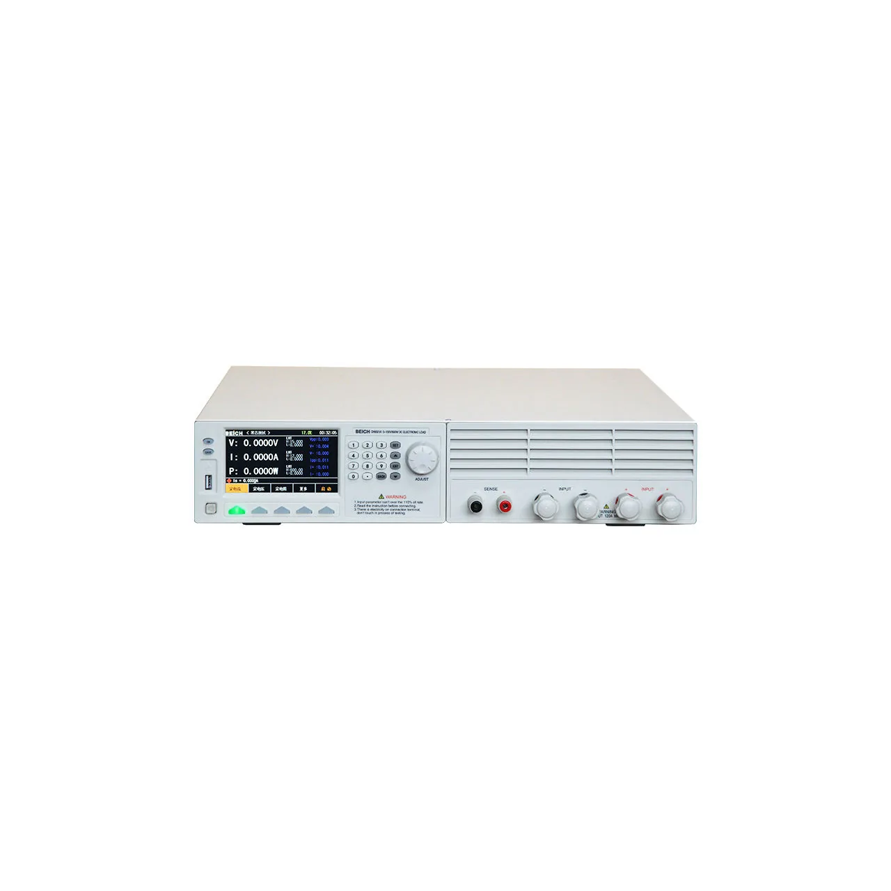
Off-white benchtop load seen from the front, with a colour screen at the left showing voltage, current and power readings, a numeric keypad and adjustment knob beside it, ventilation slots across the right-hand half and two pairs of input terminals with sense terminals along the bottom right

CH6321A (5 models) · Electrical Test Equipment

Programmable DC Electronic Load

Programmable DC electronic load with 150 V and 500 V inputs, 60 to 240 A, 600 to 1500 W, six load modes and battery, dynamic and OCP test functions.

Input voltage
0 to 150 V on four models; 0 to 500 V on four models
Input current
0.1 mA to 60 A, 120 A or 240 A depending on model
Input power
600 W, 900 W, 1200 W or 1500 W depending on model
Load modes
Constant voltage, constant current, constant power, constant resistance, short circuit and open circuit
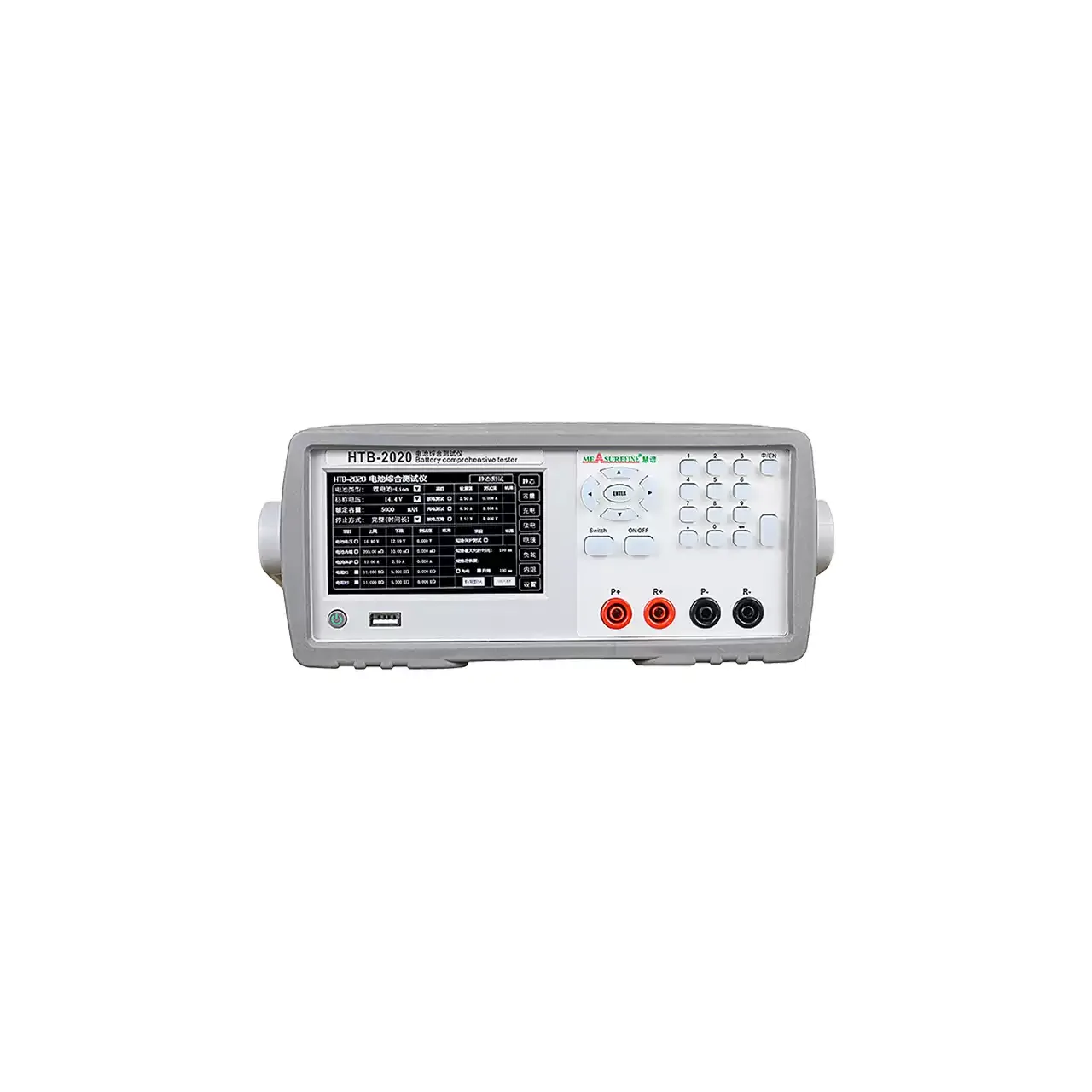
Light grey bench instrument with a liquid crystal display showing a table of battery readings on the left, a keypad with arrow keys and a numeric block on the right, and four terminals marked P+, R+, P- and R- along the lower right

HTB-2020 (2 models) · Electrical Test Equipment

Battery Capacity and Internal Resistance Tester

Two-model battery tester measuring voltage to 80 V, over-current to 20 A, internal resistance, identification resistance and capacity, with a built-in DC supply for charge and discharge.

Battery voltage range
0 to 20.000 V on HTB-2020; 0 to 80.000 V on HTB-2060, at 0.001 V
Over-current range
0 to 10.000 A on HTB-2020; 0 to 20.000 A on HTB-2060, at 0.001 A
Internal resistance
0 to 999.0 mΩ, resolution 0.1 mΩ
Identification resistance
0.1 to 999.9 kΩ, resolution 0.1 kΩ

Request a quotation for the CH9720B

Send the configuration you need and we will confirm availability, lead time and terms. Minimum order quantity is 1 pc.

Request for quotation

Request a quotation - CH9720B

Send the technical detail and we will confirm availability, lead time and terms. In-stock items ship within 48 hours; customized specifications typically take 2-10 days. Minimum order quantity is 1 pc.

The more of this you can give us, the fewer exchanges are needed before we can quote.
No file chosen
Datasheet, drawing, BOM or photograph. One file, up to 10 MB (PDF, Office, image or ZIP).

By submitting this form you agree that we may contact you about this enquiry. We do not sell or share enquiry data. See our privacy policy.

Items held in stock are dispatched within 48 hours of order confirmation. Customized specifications are produced to order and typically ship within 2 to 10 days. Transit time then depends on the shipping method and destination.

Request a Quote WhatsApp