- Voltage range
- 1 μV to 33 mV, in three ranges of 0.3, 3.0 and 30 mV
- Voltage resolution
- 1 μV
- Magnetomotive force
- 0.00 to 2.00 A, accuracy ±1%
- Sorting
- One under-limit bin, fourteen pass bins and one over-limit bin
- Test speed
- 30, 20, 13, 7 or 4 readings per second, selectable
- Trigger delay
- 0 to 9999 ms
- Display
- 240 × 128 dot-matrix LCD, direct reading or percentage, four or five digits with three decimals
- Interfaces
- HANDLER as standard; RS232 as an option
- Body
- 360 × 320 × 120 mm, about 5 kg
A soft magnetic core is not bought on a catalogue number alone. Two cores of the same size and material can differ enough to change the behaviour of the transformer or inductor they go into, and the difference shows up as a voltage across a sense winding at a given drive. This instrument reads that pair and puts the core in a bin.
Product overview
The HG2900 is a bench instrument built to sit beside a core-sorting machine. It applies a magnetomotive force of up to 2.00 A to the core and measures the voltage induced in the sense winding, from 1 μV up to 33 mV, across three ranges. The reading is compared with limits and the result is passed to the handler connector.
It is also a standalone instrument. With no sorting machine attached it works as an AC constant current source or as an AC millivoltmeter, which is useful on a bench that characterises a few cores by hand before a line is set up.
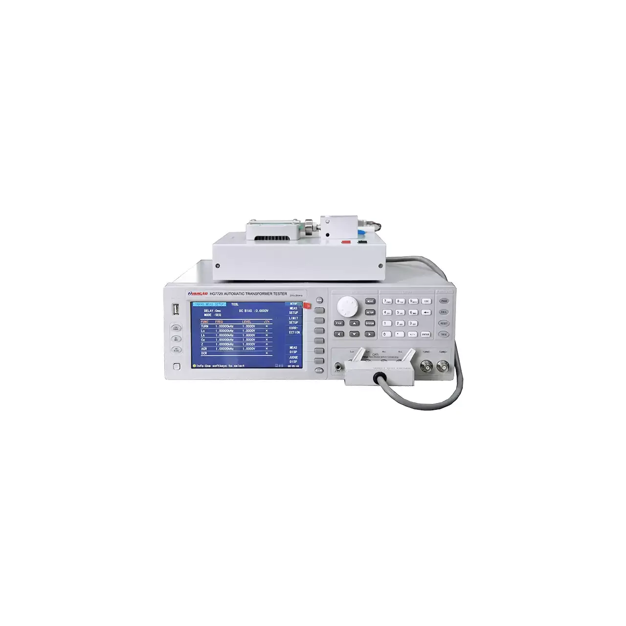
The front panel carries the display at the left, soft keys beside it, a direction pad and numeric keypad at the right, and the test sockets along the lower edge. The body is 360 mm wide and about 5 kg.
How the core tester works
The core is wound, or is already wound, with a drive winding and a sense winding. The instrument drives current through the drive winding and reads the voltage that appears on the sense winding. The drive current, reported as magnetomotive force, sets the operating point; the sense voltage is the response of that core at that point.
The terminals are arranged for a four-wire connection: HD and HS carry the drive, LD and LS carry the sense, with a ground terminal alongside. Separating the two paths keeps the resistance of the lead and of the fixture out of the voltage reading, which matters when the reading is measured in microvolts.
Sorting works on a band rather than a single limit. One bin is reserved for cores below the lower limit, one for cores above the upper limit, and fourteen bins sit between them for grading. The test speed and a trigger delay are part of the same decision: the delay holds the measurement back after the fixture closes, so the drive has time to settle before the reading is taken.
How to select the right core tester
The first question is what the core drawing specifies. If it gives a voltage window at a stated drive, the instrument can be set against it directly. If it only gives a grade, the fourteen pass bins are what turns a grade into a sorting rule.
The second is the winding. The voltage a sense winding produces depends on how many turns it has, so the same core with a different sense winding gives a different number. The fixture, the turns and the drive level have to be fixed before limits mean anything, and they have to be the same on the line as they were on the bench where the limits were set.
The third is throughput. Thirty readings per second suits a machine that presents cores continuously; four per second is for a core whose reading needs time to settle. Choosing the faster speed on a core that has not settled produces a number, not a measurement.
The fourth is the interface. The handler connector carries the bin decision, and the serial link, listed as an option, carries the readings to a computer. A bench that only sorts needs the first and not the second.
Send the core drawing, the winding details and a sample, and the limits and fixture can be worked out against them.
Measurement limitations and selection considerations
The instrument reports a point, not a curve. It gives the voltage at one drive level, so it describes the core where the line will use it, but not the shape of the magnetisation characteristic across the whole range. A design that needs the curve needs a plotting instrument.
The reading depends on the drive. Magnetomotive force is the product of current and turns, so a fixture that changes the number of drive turns changes the operating point even when the current is the same. That is why the winding is part of the measurement rather than a detail of the fixture.
Frequency matters in the same way. The material gives a frequency setting on the instrument but does not state the drive frequency or the waveform, so a limit established on one instrument cannot be assumed to transfer to another without checking the drive conditions first.
The voltage being read is small, in the microvolt to millivolt region. Thermal EMF in the fixture, contact resistance and lead movement are all comparable with the signal, which is why the four-wire terminals, a stable fixture and a settled trigger delay are not optional refinements.
Finally, core temperature shifts the result. A core measured straight from a delivery box and one measured after an hour of running are not at the same point on the characteristic, so the limits should be tied to the condition the parts will actually be in.
Every value below is taken from source documentation. Where a parameter is not stated in the available material it is marked as information required rather than estimated.