Electrical Test & Measurement · Electrical Test Equipment

Piezo Buzzer Plate Parameter Tester

Benchtop tester for piezoelectric buzzer plates, measuring equivalent resistance Rs and resonant frequency Fs, with seven-bin sorting, three test speeds and a HANDLER interface.

HG2788 ·

Key specifications

Parameters measured
Equivalent resistance Rs and resonant frequency Fs
Basic accuracy
±1% ±5 Ω
Resistance display
25 Ω to 2200 Ω; the display-range row gives a 20 Ω lower limit
Frequency display
0.8 kHz to 19.99 kHz
Sorting
Seven bins, with a HANDLER output
Test speed
18, 8 or 4 readings per second, selectable
Display
240 × 128 dot-matrix LCD, read-only or percentage mode
Interfaces
HANDLER as standard; RS232 as an option
Body
330 × 130 × 335 mm, about 5 kg

A buzzer plate is bought against two numbers: the frequency at which it rings, and the resistance it presents at that point. A general-purpose bridge can report one of them at a time and neither as a sorted result. This instrument is built around reading both and putting the plate into a bin.

Product overview

The HG2788 is a single-purpose bench instrument for piezoelectric buzzer plates. It measures equivalent resistance Rs and resonant frequency Fs, displays them together, and compares each against the limits set for one of seven bins. There is one model in the material; the differences a buyer chooses between are the sorting arrangement and the interface, not the measurement.

The front panel has the display at the left, a column of soft keys beside it, a direction pad and numeric keypad at the right, and the two test sockets along the lower edge. The body is 330 mm wide and weighs about 5 kg, so it sits on a bench beside a fixture rather than in a rack. The rear panel carries the HANDLER connector, the fuse and the mains inlet.

How the buzzer plate tester works

The plate is connected on a four-wire Kelvin lead. Current is delivered on one pair of conductors and the voltage is sensed on the other, so the resistance of the lead and of the socket does not add to the plate. That matters here because the quantity being read can be small: a few tens of ohms on a plate that is behaving correctly, and a reading that would otherwise move every time the lead was reseated.

The instrument drives the plate and resolves the frequency at which it resonates, reported as Fs, together with the equivalent resistance at that point, reported as Rs. Each reading is compared with the limits held for the bin. When the comparison is done the decision is available on the HANDLER connector, which is what allows a sorting machine to divert the part without an operator watching the screen.

Two display modes change what the operator sees rather than what is measured. Read-only shows the value; percentage shows it against a nominal, which is the quicker read when a line runs one plate type all shift.

How to select the right buzzer plate tester

Start with the plate drawing. The two limits it gives, one for Rs and one for Fs, decide whether a seven-bin instrument is being used as a simple pass or fail gate or as a grading machine. If the drawing only gives a window, two bins are doing the work and the rest are unused; if the customer buys plates in frequency bands, the bins map onto those bands.

Then decide how the plate leaves the test. A bench where an operator loads one plate at a time needs nothing beyond the display. A line that sorts automatically needs the HANDLER connection and a fixture that presents the plate to the sockets repeatably.

Then the interface question. The serial link is listed as an option, and it is worth having only if readings are collected on a computer. It does not change the measurement.

Finally, throughput. The three speeds are a settling-time choice, not a quality choice. A plate that reads steadily at the fastest speed can be run there; one that drifts needs the slower setting, and the reading that is stable is worth more than the one that arrives sooner.

Send the plate drawing, the limits and a sample of the part, and a configuration can be proposed against them.

Measurement limitations and selection considerations

The instrument measures one plate at a time through a lead. It is not a batch tester, and the cost of testing a tray of plates is the handling time, not the measurement time.

The reading depends on how the plate is held. Contact force, contact position and the length of the lead all shift the resonant frequency of a thin piezoelectric disc, so a fixture that locates the plate the same way every time is part of the measurement rather than an accessory. The same plate measured on two different nests will not give the same number.

The test level is set by the instrument and the material does not state it. A plate characterised on a swept impedance analyzer at a known drive level is not necessarily characterised at the same level here, so a limit transferred from one instrument to the other has to be re-established on the parts, not copied.

Piezoelectric ceramics shift with temperature. A plate measured cold, straight from a delivery box, will not read the same as one that has been running in a housing. Comparing readings taken under the same conditions is more useful than comparing single numbers across a shift.

Finally, the percentage mode is a presentation of the reading against a nominal, not a correction for it. A plate outside the nominal is still outside it; the mode only makes the departure easier to see.

Features

  • One instrument measures the two numbers a buzzer plate is bought against, equivalent resistance and resonant frequency, instead of a general-purpose bridge that reports neither as a sorted result
  • Seven sorting bins, so plates can be graded into frequency or resistance bands rather than only passed or rejected
  • A HANDLER connector on the rear panel, which lets a sorting machine take the decision from the instrument instead of from an operator reading the screen
  • Three test speeds of 18, 8 and 4 readings per second, so a bench can trade settling time for throughput on parts that need it
  • Read-only and percentage display modes, the second of which shows a reading against a nominal value and suits a line checking a single plate type all shift
  • A four-wire Kelvin lead supplied with the instrument, which keeps lead and contact resistance out of a reading that can be as low as a few tens of ohms
  • A 240 × 128 dot-matrix display that shows the two measured parameters together with trigger, range, speed and frequency mode

Technical specifications

Every value below is taken from source documentation. Where a parameter is not stated in the available material it is marked as information required rather than estimated.
Measurement
ParametersEquivalent resistance Rs and resonant frequency FsStandard
Basic accuracy±1% ±5 ΩStandard
Resistance display range20 Ω ≤ R ≤ 2200 Ω, as printed on the display-range rowStandard
Equivalent resistance display range25 Ω to 2200 Ω, as printed on the row of that name in the same tableStandard
Frequency display range0.8 kHz to 19.99 kHz; the unit is not printed on the source table and kHz is taken from the instrument displayInformation required
Display modesRead-only and percentageStandard
Settings heldTrigger (single), range, speed (fine), frequency (method 1)Standard
Sorting and throughput
Sorting binsSevenStandard
Test speed18 readings per second, 8 per second or 4 per second, selectableStandard
Handler outputRear-panel D-sub connector marked HANDLER, for an automatic sorting machineStandard
Host linkRS232, listed as an option in the interface descriptionOptional
Display and controls
Display240 × 128 dot-matrix LCDStandard
On-screen statusMeasured parameters, trigger mode, range, speed and frequency mode shown togetherStandard
Front-panel keysSoft keys for test, setup, system, backspace and enter, with a direction-key pad and a numeric keypadStandard
Test socketsReference and test sockets on the front panel, for the four-wire Kelvin leadStandard
Electrical and environment
Supply220 V ±10%, 50 or 60 Hz ±5%Standard
Operating temperature0 °C to 40 °CStandard
Operating humidityBelow 90% RHStandard
Power consumptionNot stated in the materialInformation required
Ingress protectionNot stated in the materialInformation required
Mechanical
Dimensions (W × H × D)330 × 130 × 335 mm, measured by hand on the sample and quoted to the nearest millimetreStandard
WeightAbout 5 kgStandard
Supplied leadKelvin four-wire test leadStandard
Mains leadSuppliedStandard

Available models

Selection table
Model Configuration Key ranges Availability
HG2788 Piezo buzzer plate parameter tester, benchtop, with seven-bin sorting Rs 25 Ω to 2200 Ω; Fs 0.8 kHz to 19.99 kHz; 18, 8 or 4 readings per second The only model in the material

Customization

  • RS232 interface, listed as an option rather than as part of the standard build

Certification and compliance

Certification documents not yet supplied

Certifications are only published once a certificate copy can be produced, so this section is deliberately empty rather than populated with assumed approvals. Tell us which approvals your application requires and we will confirm what is available for this instrument.

Parameters still to be confirmed

The following are required for a complete specification but are not stated in the documentation supplied to us. They are listed rather than estimated:

  • The lower limit of the equivalent resistance range, printed as 20 Ω on the display-range row and as 25 Ω on the equivalent-resistance row of the same table
  • Whether the RS232 interface is standard or optional, since the interface description calls it an option while the parameter table lists it beside HANDLER without a note
  • The unit of the frequency display range, printed as 0.8K to 19.99K without a unit; kHz is taken from the instrument display rather than from the table
  • The test signal level applied to the plate, and what the frequency setting called method 1 selects
  • Power consumption
  • Ingress protection of the enclosure
  • The complete packing list, of which only the Kelvin lead and the mains lead are confirmed
  • Calibration certificate availability and standard
  • Warranty period and its terms

Frequently asked questions

What has to be confirmed before a quotation?

The limits the plate drawing gives for equivalent resistance and for resonant frequency, since those decide whether the seven bins are enough and how they should be set; whether the bench sorts by hand or through a handler; and whether readings have to reach a computer, which is the only reason to add the serial option. The plate diameter and the way it will be contacted matter as well, because the fixture is part of the reading.

Why is a four-wire lead supplied rather than a two-wire one?

Because the quantity being read can be a few tens of ohms, and the resistance of the leads and of the contact sits in series with it. On a two-wire connection that resistance is added to the plate and the reading drifts with the lead and with how well the socket is seated. Separating the current and voltage paths removes it from the result.

Can the tester be used for a piezoelectric disc other than a buzzer plate?

The material describes the instrument for piezoelectric buzzer plates only and gives no statement about other part types. A disc that resonates inside the displayed frequency band and whose resistance falls inside the displayed resistance range is measured by the same method, but whether the limits and the fixture suit it is a question for the supplier rather than something the material answers.

Related products

Other models in the same range

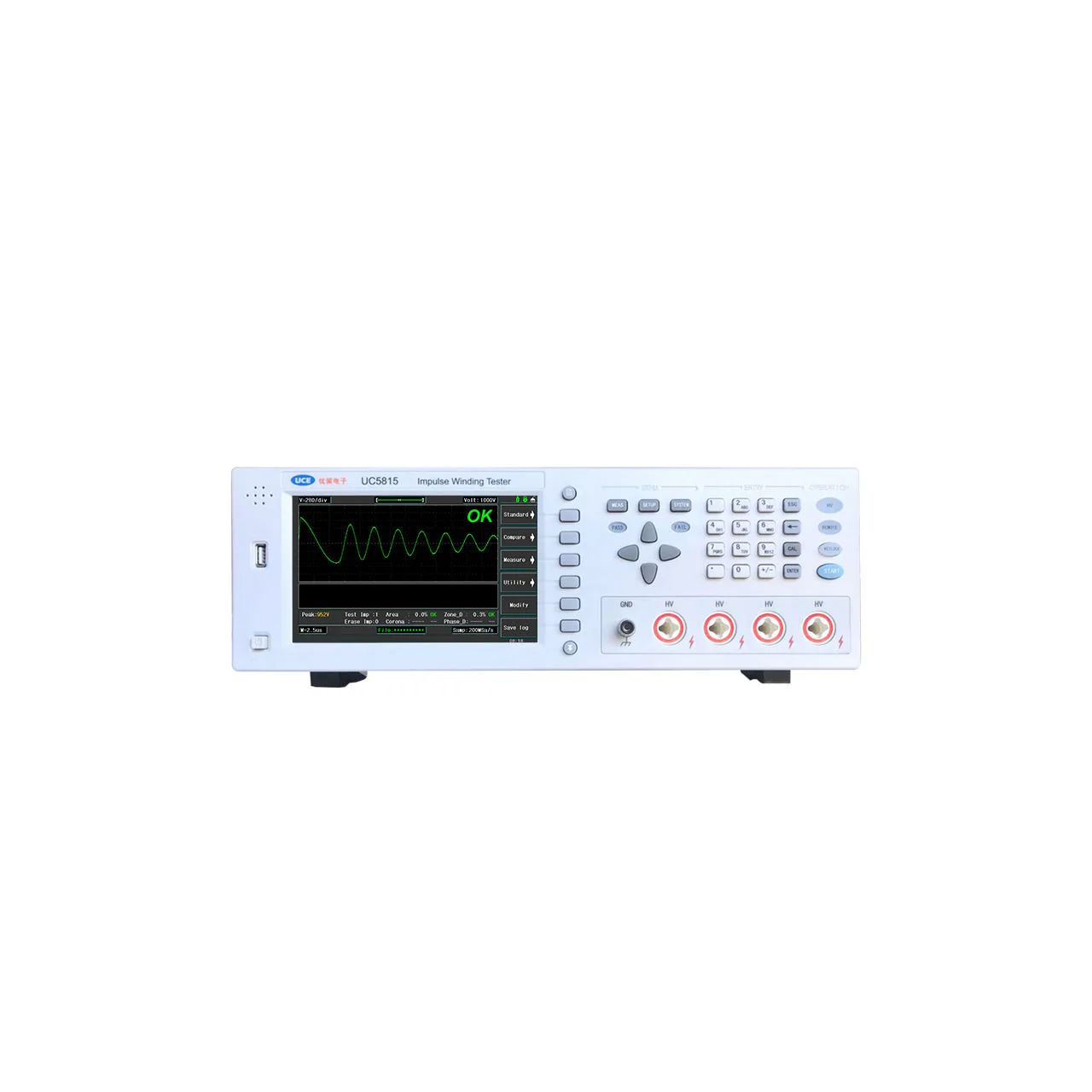
Bench instrument seen from the front, with a colour LCD showing a waveform trace across a graticule at the left, a column of soft keys beside it, a keypad and rotary controls at the right, and four high-voltage terminals with a ground terminal along the lower edge

ZX70A-200K (4 models) · LCR Meters

Impedance Analyzer for Piezoelectric and Ultrasonic Devices

Bench impedance analyzers covering 20 Hz to 5 MHz for piezoelectric ceramics, crystals and ultrasonic transducers, with four-wire Kelvin ports, frequency sweeps and a three-level comparator.

Frequency range
20 Hz to 200 kHz, 500 kHz, 1 MHz, 2 MHz or 5 MHz, by model
Basic accuracy
0.05% on the 200 kHz and 500 kHz models; 0.1% on the 1 MHz, 2 MHz and 5 MHz models
Frequency resolution
1 mHz
Impedance range
0.01 mΩ to 99.99 MΩ
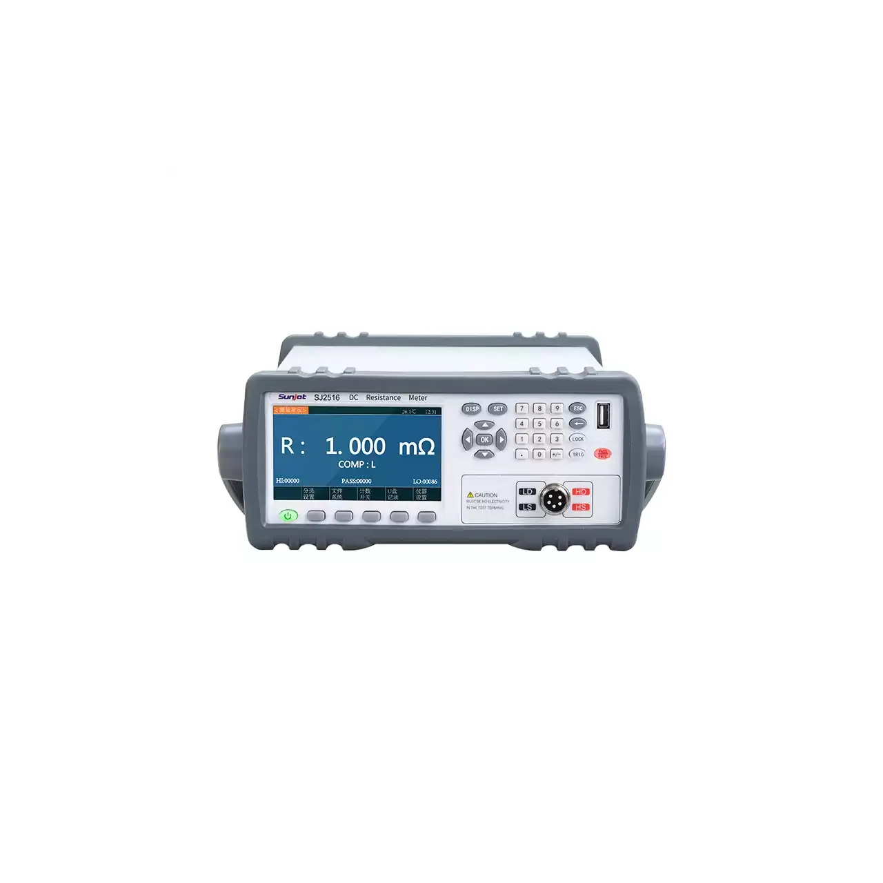
Bench resistance meter seen from the front, with a colour display reading 1.000 mΩ at the left, a numeric keypad at the right and the four test terminals at the lower right

SJ2511 (6 models) · Electrical Test Equipment

Four-Wire DC Low Resistance and Milliohm Meter

Bench four-wire DC resistance meters covering 0.01 µΩ to 2.4 GΩ across the group, with basic accuracy from 0.006% to 0.1%, test current to 10 A and three-level comparator sorting.

Test method
Four-terminal Kelvin, DC test signal
Widest range in the group
0.01 µΩ to 2.4 GΩ
Narrowest range in the group
10 µΩ to 20 kΩ
Basic accuracy
0.006% to 0.1% across the group

Request a quotation for the HG2788

Send the configuration you need and we will confirm availability, lead time and terms. Minimum order quantity is 1 pc.

Request for quotation

Request a quotation - HG2788

Send the technical detail and we will confirm availability, lead time and terms. In-stock items ship within 48 hours; customized specifications typically take 2-10 days. Minimum order quantity is 1 pc.

The more of this you can give us, the fewer exchanges are needed before we can quote.
No file chosen
Datasheet, drawing, BOM or photograph. One file, up to 10 MB (PDF, Office, image or ZIP).

By submitting this form you agree that we may contact you about this enquiry. We do not sell or share enquiry data. See our privacy policy.

Items held in stock are dispatched within 48 hours of order confirmation. Customized specifications are produced to order and typically ship within 2 to 10 days. Transit time then depends on the shipping method and destination.

Request a Quote WhatsApp