- Input voltage
- 0 to 150 V on three models; 0 to 500 V on two
- Input current
- 0.1 mA to 15 A, 30 A or 60 A depending on model
- Input power
- 150 W on CH6311A; 300 W on the other four
- Load modes
- Constant voltage, constant current, constant power, constant resistance, short circuit and open circuit
- Ripple measurement
- Vpp and Ipp with peak Vp+, Ip+ and valley Vp-, Ip-
- Accuracy
- ±(0.05% + 0.03% FS) on voltage and ±(0.05% + 0.05% FS) on current
- Resolution
- 0.1 mV and 0.1 mA on the lowest ranges; display resolution 0.0001
- Interfaces
- Isolated RS232C with SCPI, USB host and USB device
- Body
- 215 × 88 × 335 mm, about 5.5 kg or 6.5 kg
A power supply can hold its voltage perfectly and still be unusable, because the number that decides whether a circuit works is often the small AC riding on the DC. Ripple is that number, and it only exists while the supply is delivering current. Measuring it therefore belongs in the load, not on a separate bench meter.
Product overview
The CH6311A series is a programmable DC electronic load in five models. Three take 0 to 150 V and two take 0 to 500 V; current runs from 15 A to 60 A, and power is 150 W on the entry model and 300 W on the rest. Ripple measurement is fitted to every model, not offered as an option.
The load has six modes: constant voltage, constant current, constant power, constant resistance, short circuit and open circuit. Alongside them sit a dynamic test with a settable current slope, OCP and OPP capture, timing measurements for OVP, power-on and hold-up, a battery discharge mode and a 60-step list test.
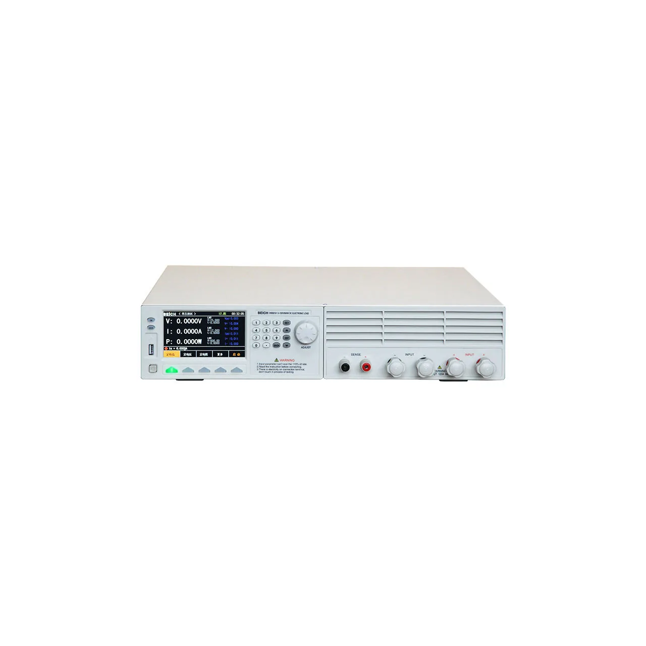
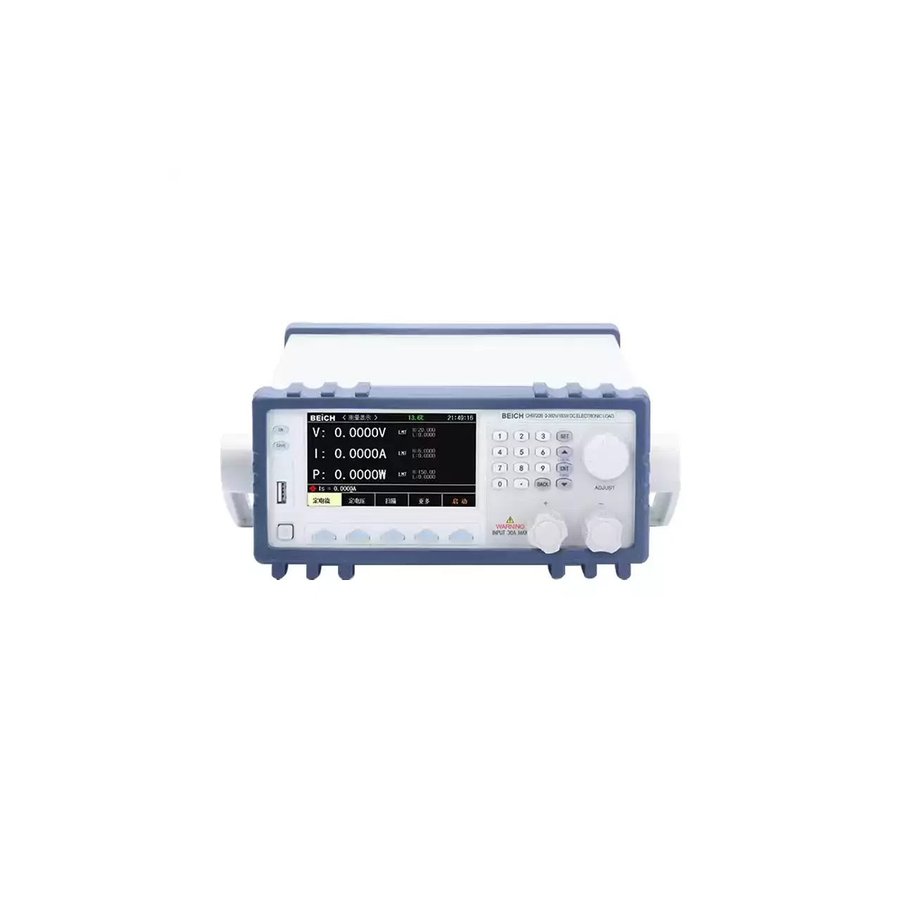
The front panel carries the display at the left, the keypad and direction keys at the right, a USB host port on the panel and the input terminals. The body is 215 × 88 × 335 mm, at about 5.5 kg on the 150 W model and 6.5 kg on the 300 W models.
How the ripple electronic load works
The load sinks a programmed current from the source and holds it there while the voltage at the terminals is sampled at 500 kHz. Because the sampling is fast relative to the ripple frequency, the waveform is captured rather than averaged, and the instrument can report the peak-to-peak value together with the highest and lowest points of the excursion.
Reporting the peaks separately is what makes the figure useful. Two supplies can show the same Vpp and behave differently: one swings symmetrically around its nominal output, the other sits at nominal and spikes upward. Vp+ and Vp- separate those cases, and the same applies to current.
The dynamic mode asks a different question. Instead of holding a steady load, it switches between two levels at a set rate with an adjustable slope, and records how the output responds. A supply that looks clean under a constant load can ring badly on a step, and the peak measurement captures that ring as it happens.
The remaining functions are built on the same stage. OCP testing raises the current until the supply protects itself and reports where that happened; the timing functions measure how long protection takes and how long the output holds after the mains is removed; the battery mode discharges a pack while accumulating capacity.
How to select the right ripple electronic load
Start with the voltage. A 150 V model covers the common adapters, chargers and low-voltage supplies; a 500 V model covers power factor corrected front ends and higher-voltage rails. The 500 V models carry less current for the same power, which is the trade the range makes.
Then the current at the voltage actually used. A 300 W model reaches 60 A only at 5 V and 15 A at 20 V, so the current figure on the model card is a maximum at low voltage rather than a figure available across the range. The 60 A model is the one to specify for a low-voltage, high-current output; the 500 V models are for the opposite case.
Then the measurements. Ripple is on every model here, which is the point of the series; OCP, timing and battery discharge are also present across the range. The choice between models is therefore about range rather than about which functions are fitted, which simplifies the selection.
Then the bench. The serial link and both USB ports are standard, with the PC software listed as an option; a hundred setups can be held in the instrument, so a line that changes product does not need a computer at every changeover.
Send the maximum voltage and current of the source, the power it delivers, and the measurements the drawing requires, and a model can be proposed against them.
Measurement limitations and selection considerations
Ripple is measured at the load terminals, which is not the same point as the output connector of the supply. The lead between them carries current and adds its own drop and pickup, so a ripple figure taken at the load includes the lead. Remote sense removes the DC drop from the voltage reading but does not remove the AC the lead picks up.
The bandwidth of the measurement sets the figure. A supply with a fast transient at 1 MHz is not described by a channel sampling at 500 kHz, whatever its Vpp reads; the number is the ripple within the instrument’s band, and the band belongs in the test record.
The power and current ratings are not simultaneous across the range. The instrument protects itself at 5% above its rated condition, so an over-power test trips rather than runs. That is the correct behaviour, but it means a test has to be designed inside the envelope rather than at its corner.
The dynamic mode’s frequency and the sampling rate are different figures, and the material states them in different places. Neither substitutes for the other: a fast dynamic mode with a slow measurement channel would switch the load faster than it could see the result.
Finally, the material does not state the mains supply or the operating temperature. Both should be confirmed before the instrument is built into a procedure, particularly in a rack where the ambient is above room temperature.
Every value below is taken from source documentation. Where a parameter is not stated in the available material it is marked as information required rather than estimated.