Electrical Test & Measurement · Insulation Resistance Testers

Insulation Resistance and Battery Short-Circuit Tester

Bench insulation tester with a 100 to 1000 V direct output, resistance measurement to 9999 MΩ, programmable rise and test times, a PLC remote interface and automatic discharge.

8205 (2 models) ·

Key specifications

Output voltage
100 to 1000 V DC, 1 V resolution, ripple below 2%
Resistance range
1 MΩ to 9999 MΩ, automatically selected
Resistance accuracy
±(2% of setting + 2 counts) from 1 to 1000 MΩ; ±(3% + 2 counts) to 9999 MΩ
Rise time
1.0 to 999.9 s in the parameter table; 0.1 to 999.9 s in the description, both carried
Test time
0 to 999.9 s, where zero means continuous
Display
Two-line, sixteen-character liquid crystal panel
Remote control
PLC interface with test, reset, three memory inputs and an interlock; pass, fail, processing and reset outputs
Discharge
Automatic at the end of the test, with a lamp showing below or above 30 V
Supply
115 or 230 V AC ±15%, 50 or 60 Hz, 3.15 A fuse
Body
280 × 89 × 390 mm, 8 kg

This instrument does one job in the older way: it applies a direct voltage, waits, and reads how much current the insulation lets through. What it adds to that is the set-up a production line needs, namely programmable times, a remote interface and an automatic discharge.

Product overview

Two models share the same measuring circuit and the same front panel layout. One performs the insulation test; the other adds a battery short-circuit function that the material names but does not specify.

The output is programmable over a decade from a hundred volts, and the resistance range reaches ten gigohms in two accuracy bands. Timing is set at both ends, a rise time before the reading and a test time during which the voltage is held.

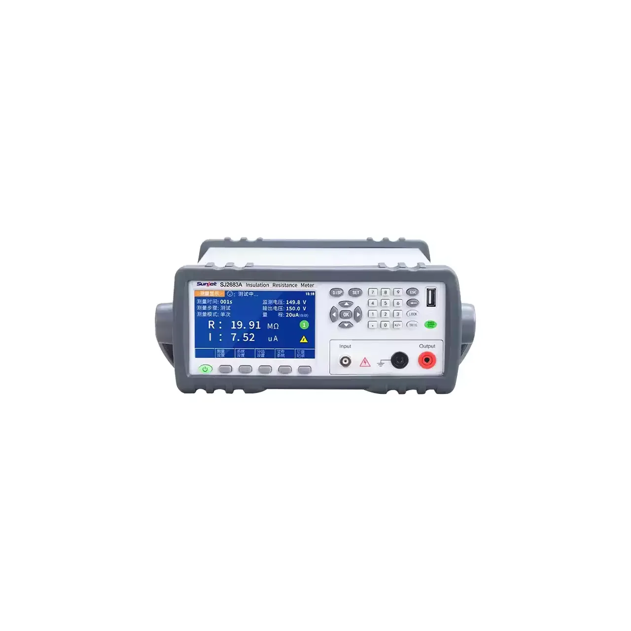
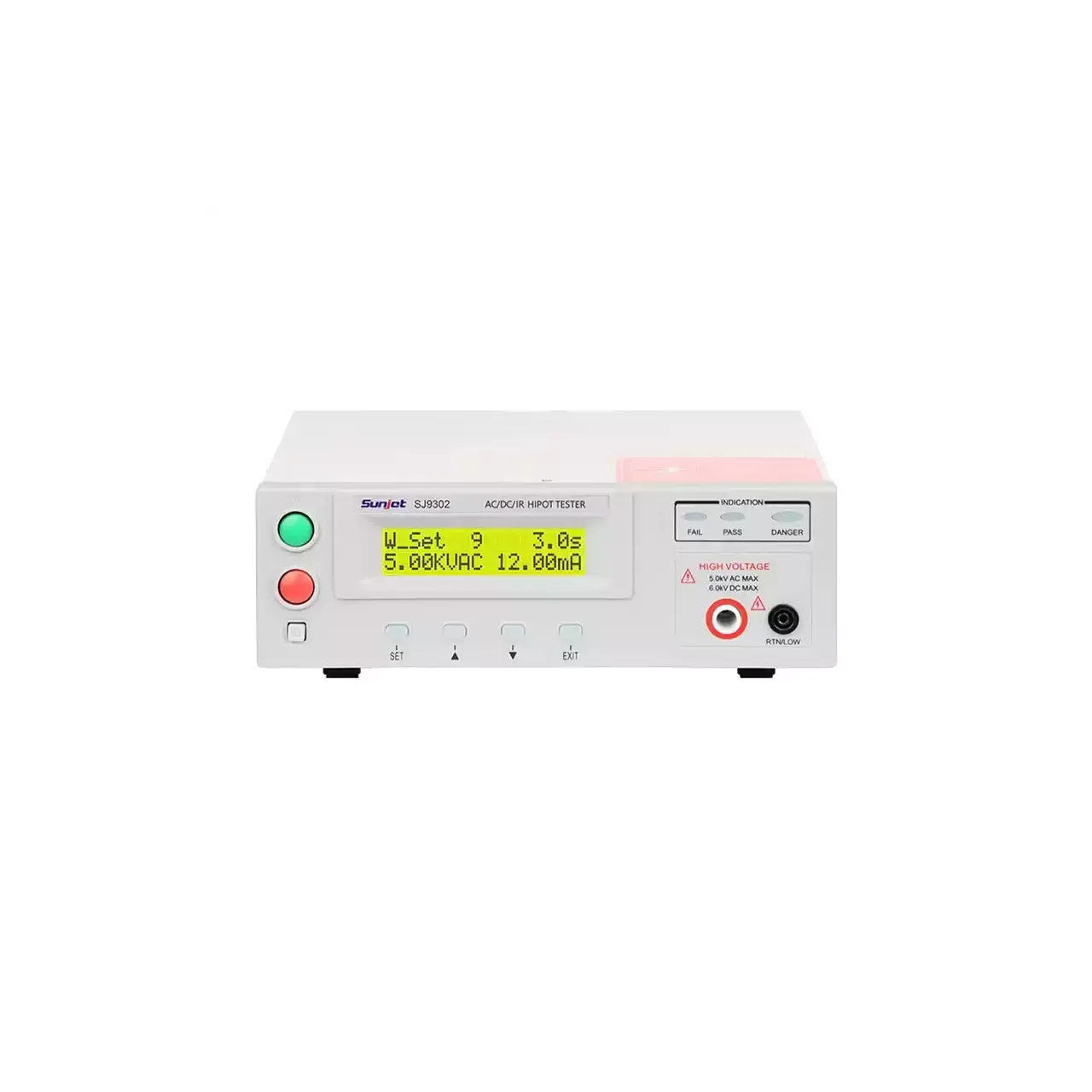
The case is a bench instrument with a carry handle and a fan at the rear, and the high-voltage terminal is an isolated type rather than a plain post.

How the meter works

The instrument raises its output to the programmed voltage over the set rise time, holds it for the test time and measures the resulting current. Resistance is the ratio of the two, and the range is selected automatically as the reading settles.

The rise time exists because insulation behaves like a capacitor. Instant application of the voltage produces a charging current far larger than the leakage, and a reading taken during that period reports a resistance far lower than the true one. Allowing the voltage to rise, then holding it, separates the charging transient from the leakage that is actually being measured.

At the end of the test the output is discharged through an internal path, and a lamp reports whether the terminals are still above thirty volts. That lamp is the difference between a safe fixture and one that surprises the next operator.

The remote interface carries the start, reset and memory selection in, and the pass, fail and processing results out. The interlock input is the one that matters for safety: it lets a fixture cover prevent a test from starting while the cover is open.

How to select the right model

The first question is whether a battery short-circuit check is part of the procedure. If it is, the second model is the only choice, and its specification has to be obtained before the instrument is specified against a criterion.

The second is the resistance band. The accuracy changes above a gigaohm, so a test that has to judge a part near the top of the range is working in the looser band, and the pass limit has to be set with that in mind.

The third is the voltage. The output starts at a hundred volts, which is below the usual five hundred volt test but above the low-voltage tests that a component-level procedure may call for.

The fourth is the interface. A bench that is driven by a fixture needs the remote inputs and the three stored settings; a bench that is driven by hand does not, and the same instrument serves both.

Measurement limitations and selection considerations

The measurement range starts at a megaohm. That is a high floor: a contaminated assembly or a failed small component can read below it, and the instrument will report an over-range condition rather than a low resistance. Where low resistances have to be judged, a different instrument is required.

The accuracy is quoted against the setting rather than against the reading in the upper band, which is a distinction that matters when the reading is far from the limit. It also changes at a gigaohm, so a single accuracy figure does not describe the instrument across its range.

The panel marking of five kilovolts alternating and six kilovolts direct is well above the programmable output and should not be read as the working range. It describes the insulation of the output stage, and a quotation that repeats it as a capability would be wrong.

Nothing in the material describes the measurement method in detail, the time at which the reading is taken, or the standard the accuracy is quoted against. Those are the questions that decide whether the instrument can be used for a compliance test rather than a production check.

Features

  • A programmable output from 100 V upwards, so a low-voltage component is tested at its own rating rather than at a fixed mains-level voltage
  • Rise time and test time set separately, which lets a capacitive item charge before the reading is taken and holds the voltage for a defined period afterwards
  • Automatic discharge at the end of the test with a lamp that shows whether the terminals are still above 30 V, which is the safety feature that matters on a production bench
  • A PLC remote interface with three stored settings and an interlock input, so the instrument can be driven by a fixture rather than by an operator
  • Four-bin sorting through the pass, fail and processing outputs, which is what a line needs to route a part rather than only to stop it
  • A key lock set at power-on, which keeps a validated set-up from being changed between shifts
  • An isolated high-voltage output terminal and a BNC return, which is a safer arrangement than two unshielded posts at these voltages

Technical specifications

Every value below is taken from source documentation. Where a parameter is not stated in the available material it is marked as information required rather than estimated.
Output
Voltage100 to 1000 V DC, 1 V resolutionStandard
Voltage accuracy±(1% of setting + 1 V)Standard
Output regulation±(1% of output + 1 V) from no load to full loadStandard
RippleBelow 2%Standard
Output terminalsIsolated high-voltage output terminal and a BNC return terminalStandard
Panel markingBoth panels carry 5.0 kV AC and 6.0 kV DC maximum, which is a warning marking rather than the programmable rangeInformation required
Measurement
Resistance range1 MΩ to 9999 MΩ, range selected automaticallyStandard
Resistance accuracy±(2% of setting + 2 counts) from 1 to 1000 MΩ; ±(3% + 2 counts) from 1000 to 9999 MΩStandard
Accuracy below 1 MΩThe accuracy table has entries at 0.1 MΩ for two voltage bands but gives no figure; the measurement range itself starts at 1 MΩInformation required
Voltage readout0 to 100 V at 0.1 V resolution and 101 to 1000 V at 1 V resolution, ±(1% of setting + 1 V)Standard
Lower and upper resistance limits0.1 to 999.9 MΩ at 0.1 MΩ resolution, and 1000 to 9999 MΩ at 1 MΩ resolution; the accuracy cell for the upper band is illegible in the materialInformation required
Measurement methodNot stated in the material beyond the applied voltage and the resistance rangeInformation required
Timing and control
Rise time1.0 to 999.9 s at 0.1 s resolution in the parameter table; the descriptive page gives 0.1 to 999.9 sInformation required
Test time0 to 999.9 s at 0.1 s resolution; zero gives continuous testingStandard
Timing accuracy±(0.1% + 0.05 s)Standard
PLC inputsTest, reset, memory 1, 2 and 3, and interlockStandard
PLC outputsPass, fail, processing and reset outStandard
Key lockSet and up held at power-on, then a menu choice of on or offStandard
CalibrationFrom the front panel, by softwareStandard
MemoryThree stored settings, selected from the remote interfaceStandard
Environment and physical
Operating environment0 to 40 °C, 20 to 80% relative humidityStandard
Dimensions280 mm wide, 89 mm high, 390 mm deep on the dimension drawing; the general characteristics line gives the same three figures in a different orderStandard
Weight8 kgStandard
Front panelDisplay, reset button, test button, function keys, test terminals and power switchStandard
Rear panelCooling fan, fuse, mains voltage selector, earth terminal, calibration key, remote signal terminals, serial socket and mains inletStandard
Supplied accessoriesAn insulation test lead listed for both models; the material gives no other carton contentsStandard
Ingress protectionNot stated in the materialInformation required

Available models

Selection table
Model Configuration Key ranges Availability
8205 Insulation test only 100 to 1000 V DC; 1 MΩ to 9999 MΩ The insulation model
8210 Insulation test with a battery short-circuit check 100 to 1000 V DC; 1 MΩ to 9999 MΩ; short-circuit function added The material names the function but gives it no separate parameters

Customization

  • The mains voltage setting, 115 or 230 V
  • The test lead, which the material names for both models but does not describe further
  • The stored settings, three of which can be configured and recalled over the remote interface

Certification and compliance

Certification documents not yet supplied

Certifications are only published once a certificate copy can be produced, so this section is deliberately empty rather than populated with assumed approvals. Tell us which approvals your application requires and we will confirm what is available for this instrument.

Parameters still to be confirmed

The following are required for a complete specification but are not stated in the documentation supplied to us. They are listed rather than estimated:

  • The short-circuit test specification of the 8210: current limit, trip threshold, test time and pass criterion
  • Whether the rise time starts at 0.1 s or at 1.0 s, since the parameter table and the description disagree
  • The resistance accuracy below 1 MΩ, which the accuracy table leaves blank although the limit setting reaches 0.1 MΩ
  • The accuracy of the 1000 to 9999 MΩ limit setting, whose cell is illegible in the material
  • Whether the 1 MΩ figure is the measurement floor or only the display floor, since the limit setting and the accuracy table both mention 0.1 MΩ
  • The meaning of the 5 kV AC and 6 kV DC panel marking against the 1 kV programmable output
  • The measurement method used, and whether the reading is taken at a fixed time after the voltage is applied
  • The standard the accuracy figures are quoted against, and calibration certificate availability
  • The full contents of the shipping carton
  • Ingress protection and the maximum altitude of operation
  • Warranty period and its terms

Frequently asked questions

What does the battery short-circuit function add?

The material names it on the 8210 and gives the model the description of a battery short-circuit and insulation tester, but the two models share one parameter table and no short-circuit specification appears in it: no current limit, no trip threshold and no test time. Until those figures are supplied, the 8210 should be quoted for the function and not specified against a short-circuit criterion.

Why does the panel say 5 kV when the output is 1 kV?

The panel marking is a warning label for the output stage, not the programmable range. The parameter table gives 100 to 1000 V DC. A panel figure three to six times the stated output is common on instruments whose high-voltage transformer and insulation are rated above the working range, but the two numbers should not be read as alternatives and the point is worth confirming in writing.

What has to be confirmed before a quotation?

The test voltage and whether it has to go below 100 V; the resistance band that has to be judged, since the accuracy changes above a gigaohm; the rise and test times the procedure requires; whether a PLC drives the instrument and which of the three memories it uses; and whether the short-circuit function is needed, in which case its specification has to be obtained first.

Related products

Other models in the same range

Benchtop insulation resistance meter in a grey case with a carrying handle, a colour screen at the left showing resistance and current readings above a row of soft keys, a numeric keypad at the right and three terminals labelled Input and Output below it

SJ2682A (6 models) · Insulation Resistance Testers

Programmable Digital Insulation Resistance Meter

Benchtop insulation resistance meter with programmable direct voltage from 0.5 V, resistance ranges to 100 PΩ on the top model, micro-current measurement from 0.1 fA and four-bin sorting.

Resistance range
10 kΩ to 1 TΩ on the entry model; 0.1 kΩ to 100 PΩ on the top model
Test voltage
Direct, 10 to 1000 V in 1 V steps, or 0.5 to 1000 V in 0.1 V steps by model
Current range
1 mA down to 0.01 pA, 0.01 nA, 0.01 pA or 0.1 fA by model
Resistance accuracy
±2% or ±3% below 1 GΩ, ±5% above 1 GΩ, ±10% above 1 TΩ
Programmable withstand voltage and insulation tester shown from the front, with the two-line backlit LCD at the top left, the function keys below it and the high-voltage output terminals along the lower edge

SJ7110 (6 models) · Electrical Safety Testers

Programmable Withstand Voltage and Insulation Tester

Programmable safety tester range applying up to 5 kV AC or 6 kV DC, measuring leakage current against preset limits and insulation resistance to 50 GΩ, with arc detection and ten memory groups.

AC output
0.10 kV to 5.00 kV
DC output
0.10 kV to 6.00 kV, on five of the six models
Leakage current
0 to 12.00 mA AC and 0 to 5.00 mA DC as standard; 20 mA and 10 mA on the largest model
Insulation resistance
1 MΩ to 10 GΩ on the mid range; 0.1 MΩ to 50.0 GΩ on the two largest models

Request a quotation for the 8205

Send the configuration you need and we will confirm availability, lead time and terms. Minimum order quantity is 1 pc.

Request for quotation

Request a quotation - 8205

Send the technical detail and we will confirm availability, lead time and terms. In-stock items ship within 48 hours; customized specifications typically take 2-10 days. Minimum order quantity is 1 pc.

The more of this you can give us, the fewer exchanges are needed before we can quote.
No file chosen
Datasheet, drawing, BOM or photograph. One file, up to 10 MB (PDF, Office, image or ZIP).

By submitting this form you agree that we may contact you about this enquiry. We do not sell or share enquiry data. See our privacy policy.

Items held in stock are dispatched within 48 hours of order confirmation. Customized specifications are produced to order and typically ship within 2 to 10 days. Transit time then depends on the shipping method and destination.

Request a Quote WhatsApp