- Resistance range
- 10 kΩ to 1 TΩ on the entry model; 0.1 kΩ to 100 PΩ on the top model
- Test voltage
- Direct, 10 to 1000 V in 1 V steps, or 0.5 to 1000 V in 0.1 V steps by model
- Current range
- 1 mA down to 0.01 pA, 0.01 nA, 0.01 pA or 0.1 fA by model
- Resistance accuracy
- ±2% or ±3% below 1 GΩ, ±5% above 1 GΩ, ±10% above 1 TΩ
- Voltage accuracy
- 0.25% ±0.25 V at or below 10 V; 0.5% ±0.5 V above 10 V
- Ranging
- Seven ranges, automatic or manual, with a lock position
- Measurement speed
- Five readings per second slow, twelve per second fast
- Sorting
- Three record groups and four bins, three pass and one fail
- Display
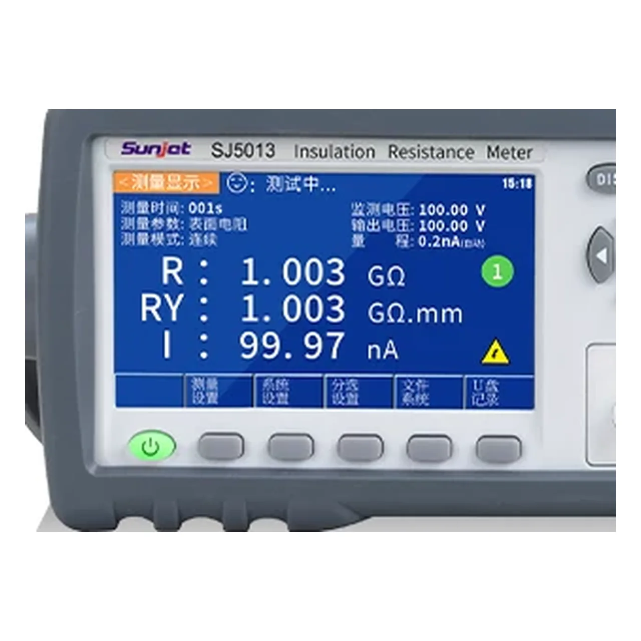
- 4.3 inch colour liquid crystal screen, four digits
- Interfaces
- RS232C, HANDLER and USB as standard; RS485 on the 2683 models as carded
An insulation tester is bought for the top of its range, but it is chosen at the bottom. The highest resistance it can resolve is set by the smallest current it can measure, and that figure, not the voltage, decides whether a good insulator is distinguished from a perfect one.
Product overview
Six models share one bench instrument: a colour screen, a numeric keypad, a guarded three-terminal input and a programmable direct voltage. They separate along three lines, the voltage ceiling, the resistance ceiling and the current floor.
The four tabled models form two pairs. Within a pair the voltage ceiling halves from one kilovolt to five hundred volts while the resistance range falls with it; between pairs the higher pair adds a decade of resistance resolution at the top and a lower starting voltage. The two remaining models extend the resistance range into the petaohm region and are described only on their cards.
The case is a bench instrument with a carrying handle, not a handheld, and it is intended for a production position or a laboratory bench rather than for site work.
How the meter works
A direct voltage is applied between the output terminal and the item, and the current that flows is measured at the sense input. Resistance is the ratio of the two, computed by the instrument and shown directly. Because the current is the measured quantity, the highest resistance the instrument can report is fixed by the smallest current it can resolve, which is why the range and the current floor move together across the models.
The third terminal is the guard. Surface leakage on a humid day can exceed the current through the insulation itself; connecting a conductive collar around the item to the guard diverts that surface current away from the sense input, so the reading reflects the volume path rather than the surface path.
The test is timed in two parts. A charge time lets a capacitive item settle, and a measurement delay holds the reading back until the current has stopped falling. Both are set by the user, which matters because a reading taken before the current settles is always too low in resistance and too optimistic about the item.
How to select the right model
Begin with the test voltage the component or the standard requires. If the requirement is a kilovolt, the 500 V models are excluded; if the requirement is below one volt, only the 2683 and the two petaohm models can set it.
Then the resistance that has to be distinguished. Testing a cable insulation to a gigaohm and testing a polymer film to a teraohm are different measurements with different floors, and a model chosen on voltage alone may not reach the figure that matters.
Then the current floor, which follows from the resistance and is the same decision seen from the other side. Finally the interface: RS485 appears only on the 2683 models, and a line that is already wired for it should not have to add an adapter.
Sorting and the key lock are production features rather than measurement ones, but they decide whether the instrument can run a position on its own.
Measurement limitations and selection considerations
The accuracy is binned by decade, not stated as a single figure. A resistance just above a gigaohm carries a five per cent tolerance and one above a teraohm ten per cent, so the useful question is not the tightest figure quoted but which bin the measurement falls in.
Insulation resistance is not dielectric strength. This instrument measures how much current leaks at a voltage well below breakdown; a withstand voltage test measures whether the insulation survives a higher voltage for a time. The two are separate tests with separate instruments, and passing one says nothing about the other.
Above a teraohm the measurement becomes an environmental one. Humidity, surface contamination, lead insulation and the geometry of the item all contribute currents of the same order as the one being measured, and the guard, the shielded leads and a controlled environment are part of the measurement rather than accessories to it.
Finally, the material describes two models with card specifications only. A quotation for those should be based on a full parameter table, not on the model list alone.
Every value below is taken from source documentation. Where a parameter is not stated in the available material it is marked as information required rather than estimated.