Industrial Automation & Control · Signal Converters

AC Current and Voltage Transducer

A DIN-rail current and voltage transducer for AC or DC circuits, with 4-20 mA, 0-10 V, RS-485 or CAN output, split-core and through-bore inputs to 3000 A, and 0.2 to 0.5 class accuracy.

Key specifications

Input
AC current from 0-5 A to 0-3000 A, AC voltage to 500 V, DC current and voltage, with split-core and through-bore forms
Output
4-20 mA, 0-20 mA, 0-10 V, 0-5 V, RS-485/Modbus or CAN
Accuracy
0.2, 0.3 or 0.5 class, with plus or minus 0.1 % and 0.2 % of full scale on some forms
Supply
24 V DC, 220 V AC or 12 V DC depending on the form
Frequency range
50 to 400 Hz on the AC forms, with a 0-20 kHz bandwidth on the wideband form
Power consumption
1.5 W or less on the one-in/one-out 220 V form
Mounting
DIN rail, with through-bore or split-core input
Isolation
Galvanic isolation between input, output and supply

A controller cannot be wired into a live feeder. A current transducer is the device that makes the measurement possible without opening the circuit: it takes the current or voltage, isolates it, and sends a standard signal to whatever is doing the reading.

The distinction that matters in a quotation is that this is not a panel meter. It has no display. It is read by a PLC, a logger or a drive, and the person who specifies it is usually the one wiring the control panel rather than the one standing at the machine.

Product overview

The device is a DIN-rail module with a through-bore or a split core for the primary conductor, screw terminals for the output and supply, and electronics that convert the measured quantity into a standard signal.

The material covers AC current from 0-5 A to 0-3000 A, AC voltage to 500 V, DC current and voltage, and three-phase power and frequency. Output is 4-20 mA, 0-20 mA, 0-10 V, 0-5 V, RS-485/Modbus or CAN, depending on the form. Supply is commonly 24 V DC, with 220 V AC and 12 V DC versions.

How a current transducer works

Three input methods appear in the material, and the difference between them is practical rather than theoretical.

A through-bore form passes the conductor through a hole in the device and senses the field around it. It is the simpler and more compact of the three, and it requires the circuit to be opened once, during installation.

A split core clamps around a cable or a busbar that is already terminated. It is what makes a retrofit possible on a 3000 A feeder, and its weakness is the joint: the two halves have to close cleanly, and a poor joint reads low rather than failing.

A direct voltage input takes the voltage across its terminals through a divider, which is why the voltage forms are rated to 500 V rather than to a current.

In every case the output is isolated from the input, which is what allows a 3000 A feeder and a 24 V control system to share an enclosure.

How to select the right transducer

AC or DC, and how many phases. A single-phase current form and a three-phase power form are different products. The three-phase form is specified by its connection — three-wire or four-wire — rather than by current alone.

Whether the circuit can be opened. This decides between through-bore and split core, and it is usually known before anything else. A retrofit on a live feeder has one answer; a new panel has the other.

Output and protocol. 4-20 mA is the default for a PLC analogue card. RS-485/Modbus or CAN is used where several parameters are read over one bus. The controller decides this, not the transducer.

Accuracy class. 0.2, 0.3 and 0.5 class are all offered. A finer class costs more and matters where the reading feeds a bill or a compliance record; for a status signal the coarser class is enough.

Installation and configuration

The module clips onto a DIN rail in the control enclosure. The primary conductor passes through the bore or sits in the split core, and the output is wired to the controller with the supply.

The practical points are the direction of the conductor, the tightness of a split core, and the separation between the primary cable and the output wiring. The material gives no wiring diagram, no torque and no clearance distances, and none is invented here.

Measurement limitations and selection considerations

The first limitation is that a transducer measures what passes through it. A conductor outside the bore, or a split core that does not close, gives a reading that is plausible and wrong.

The second is that the output is a scaled copy of the input, not a true RMS measurement on every form. The material states a frequency range of 50 to 400 Hz on the AC forms and a 0-20 kHz bandwidth on one wideband form; a distorted waveform outside that band is not represented faithfully.

The third is that several figures are missing: the isolation voltage, the enclosure rating, the ambient range and the long-term drift. They are listed as information required rather than filled in from a similar device.

Features

  • A standard output from a circuit that cannot be wired directly to a controller, which is the reason the device exists: 4-20 mA, 0-10 V, RS-485 or CAN from a live conductor
  • Through-bore and split-core inputs, so a cable can be passed through the device or the device can be clamped around a cable that is already terminated
  • AC current to 3000 A on the split-core form, and AC voltage to 500 V, without breaking the circuit
  • 0.2, 0.3 and 0.5 class forms, so a revenue-adjacent measurement and a status signal are not priced the same
  • Galvanic isolation between input, output and supply, which is what makes the output safe to connect to a PLC
  • DIN-rail mounting, so the device sits in the same enclosure as the controller it feeds

Technical specifications

Every value below is taken from source documentation. Where a parameter is not stated in the available material it is marked as information required rather than estimated.

Input
AC current0-5 A, 0-10 A, 0-20 A, 0-30 A, 0-50 A and 0-100 A through-bore forms; 50 A to 3000 A on the split-core formStandard
AC voltage0-100 V, 0-380 V and 0-500 V formsStandard
DC current and voltageDC current and voltage inputs are listed alongside the AC formsStandard
Frequency50 to 400 Hz on the AC formsStandard
Bandwidth0-20 kHz on the wideband frequency formStandard
Input typeThrough-bore, split-core, current-transformer and direct-voltage, depending on the formStandard
Output and supply
Analogue output4-20 mA, 0-20 mA, 0-10 V and 0-5 VStandard
Digital outputRS-485/Modbus or CAN, depending on the formStandard
Relay outputRelay contacts on the forms that carry an alarmStandard
Supply24 V DC as the common form, with 220 V AC and 12 V DC versionsStandard
Power consumption1.5 W or less on the one-in/one-out 220 V formStandard
IsolationGalvanic isolation between input, output and supply; the isolation voltage is not statedInformation required
Terminal assignmentTerminals 3 and 4 input, 5 and 6 output, 7 and 8 supply, as marked on the unitStandard
Nameplate, unit shownINPUT AC 0-400 V, CLASS 0.2 %FS, POWER DC 24 V, OUTPUT DC 4-20 mAStandard
Accuracy
Accuracy class0.2, 0.3 and 0.5 class, with plus or minus 0.1 % and 0.2 % of full scale on some listingsStandard
Long-term stability0.3 class is described as held long-term, without a drift figureInformation required
Temperature effectNot stated in the materialInformation required
Response timeNot stated in the materialInformation required
Mechanical and environment
MountingDIN railStandard
EnclosureNot stated in the materialInformation required
Ingress protectionNot stated in the materialInformation required
Ambient temperatureNot stated in the materialInformation required
TerminalsScrew terminals; the conductor passes through the bore or sits in the split coreStandard

Available models

Selection table
Model Configuration Key ranges Availability
Through-bore AC current Conductor passes through the bore; 4-20 mA or 0-10 V output 0-5 A to 0-100 A; 50-400 Hz; 0.2 to 0.5 class The general form for a panel or a machine
Split-core AC current Clamps around a cable that is already terminated 50 A to 3000 A For a retrofit where the circuit cannot be opened
AC voltage Direct voltage input, isolated output 0-100 V, 0-380 V and 0-500 V Used with the current form for power measurement
Three-phase power and frequency Three-phase three-wire or four-wire input, with active, reactive and apparent power or frequency output 4-20 mA per phase, or RS-485 For a feeder rather than a single load
RS-485 or CAN communication Digital output on Modbus or CAN Multi-parameter: current, voltage, power, energy For a plant that reads several parameters over one bus

Customization

  • Input range, from a 0-5 A through-bore to a 0-3000 A split core
  • Output, as 4-20 mA, 0-10 V, 0-20 mA, RS-485/Modbus or CAN
  • Supply, as 24 V DC, 12 V DC or 220 V AC
  • Number of channels, as one-in/one-out or one-in/two-out
  • Function, as current only, voltage only, or a multi-parameter form covering power and frequency

Certification and compliance

Certification documents not yet supplied

Certifications are only published once a certificate copy can be produced, so this section is deliberately empty rather than populated with assumed approvals. Tell us which approvals your application requires and we will confirm what is available for this instrument.

Parameters still to be confirmed

The following are required for a complete specification but are not stated in the documentation supplied to us. They are listed rather than estimated:

  • The isolation voltage between input, output and supply
  • The enclosure material and the ingress protection rating
  • The ambient temperature range
  • The long-term drift behind the 0.3 class claim
  • The temperature effect on the output
  • The response time and the output ripple
  • The accuracy basis, since a class and a percentage of full scale both appear
  • The conductor size accepted by each bore and each split core
  • The relay contact rating on the alarm forms
  • Certification and marking
  • The official model code, since the material does not give one
  • Warranty period and the terms that apply

Frequently asked questions

What is the difference between a current transducer and a panel meter?

A transducer converts the measured current or voltage into a standard signal and sends it away; a panel meter displays it locally. A transducer has no display and is read by a PLC or a logger, while a panel meter is read by a person standing in front of the panel. Some installations need both, and they are different products rather than two versions of one.

What has to be confirmed before a transducer can be quoted?

The circuit first: AC or DC, single or three phase, the nominal current and voltage, and the frequency. Then whether the circuit can be opened, because that decides between a through-bore and a split-core form. Then the output the controller accepts, the supply available in the enclosure, the accuracy class the duty needs, and the number of channels.

Why is the split-core form used for high currents?

Because a 3000 A conductor is not something that can be disconnected to pass through a bore. A split core clamps around the cable or busbar in place, which is what makes a retrofit possible. The trade-off is that the two halves must close cleanly; a poor joint shows up as a low reading rather than as a fault.

Can one device measure power as well as current?

Yes on the three-phase forms, which take three-phase three-wire or four-wire voltage and current and output active, reactive and apparent power, or frequency. Those forms are specified by the connection rather than by the current alone, so the wiring arrangement has to be stated when the order is placed.

Related products

Other models in the same range

A rectangular panel meter with a black bezel, showing a two-hundred-and-thirty volt reading in red digits and a current reading in blue digits, with a small split-core current transformer on a lead below it

AC-10A (3 models) · Panel Meters

Digital AC Panel Meter

Panel meter showing AC voltage and current together on two rows of digits, self-powered from the measured circuit and supplied with a split-core current transformer.

Voltage range
AC 60 to 500 V, for 220 V single-phase and 380 V three-phase circuits
Current ranges
10 A, 50 A and 100 A versions, the 10 A version resolving to 0.01 A
Supply
No separate supply; the measured voltage powers the instrument
Display
Two rows of digits, voltage in red and current in blue, with AC symbols on the right
Four slim DIN-rail signal isolator modules standing side by side, each with pluggable terminals on the top face

M2 · Signal Isolators

DIN-Rail Signal Isolator

DIN-rail signal isolators and distributors giving 2000 Vrms isolation between input, output and supply, with 0.1%FS transmission accuracy and 10 ms response.

Isolation
2000 Vrms for 1 min, no flashover, between input, output and supply
Insulation resistance
100 MΩ minimum at 500 VDC
Transmission accuracy
0.1%FS at 20°C
Temperature drift
0.0075%FS/°C
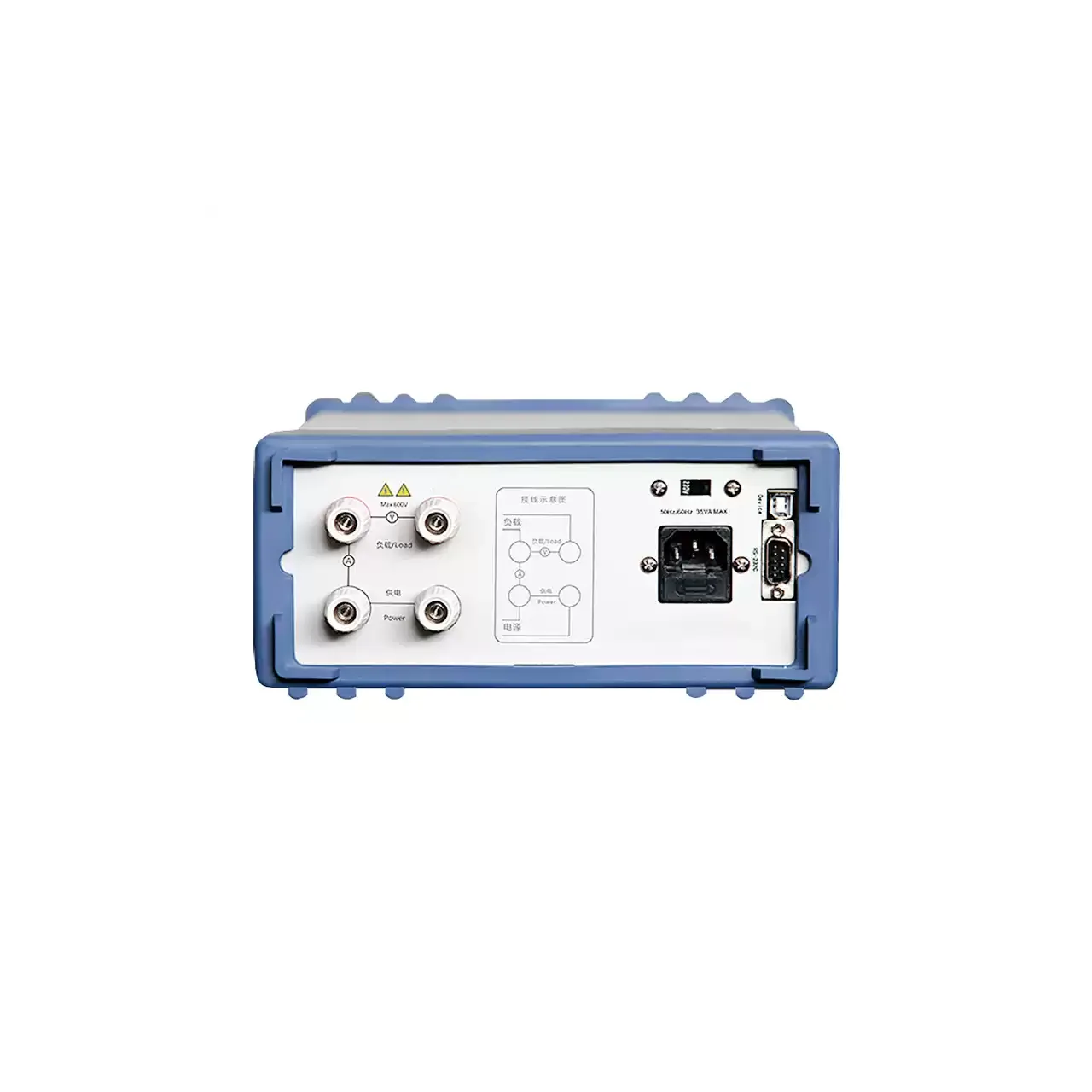
Rear panel of a bench power meter in a blue-grey case, with four binding posts in two pairs at the left, a wiring diagram between them, and a mains inlet, fuse holder, USB socket and a nine-pin serial socket at the right

CH2801 (5 models) · Power Meters

Single-Channel Digital Power Meter with Harmonic Analysis

Single-channel bench power meter with a 4.3 inch colour screen, true root mean square measurement, energy totals, and five models reaching 40 A or down to 0.05 mA, one with harmonic analysis.

Channels
One, single-phase
Voltage
5 to 600 V AC, 700 V AC peak, 0.1 V resolution
Current
10 mA to 10 A or 20 A as printed; 5 mA to 20 A, 0.05 mA to 5 A or 0.5 mA to 40 A by model
Power
0.1 W to 12 kW; 0.001 W to 3000 W on the low-current model

Request a quotation

Send the configuration you need and we will confirm availability, lead time and terms. Minimum order quantity is 1 pc.

Request for quotation

Request a quotation - AC Current and Voltage Transducer

Send the technical detail and we will confirm availability, lead time and terms. In-stock items ship within 48 hours; customized specifications typically take 2-10 days. Minimum order quantity is 1 pc.

The more of this you can give us, the fewer exchanges are needed before we can quote.
No file chosen
Datasheet, drawing, BOM or photograph. One file, up to 10 MB (PDF, Office, image or ZIP).

By submitting this form you agree that we may contact you about this enquiry. We do not sell or share enquiry data. See our privacy policy.

Items held in stock are dispatched within 48 hours of order confirmation. Customized specifications are produced to order and typically ship within 2 to 10 days. Transit time then depends on the shipping method and destination.

Request a Quote WhatsApp