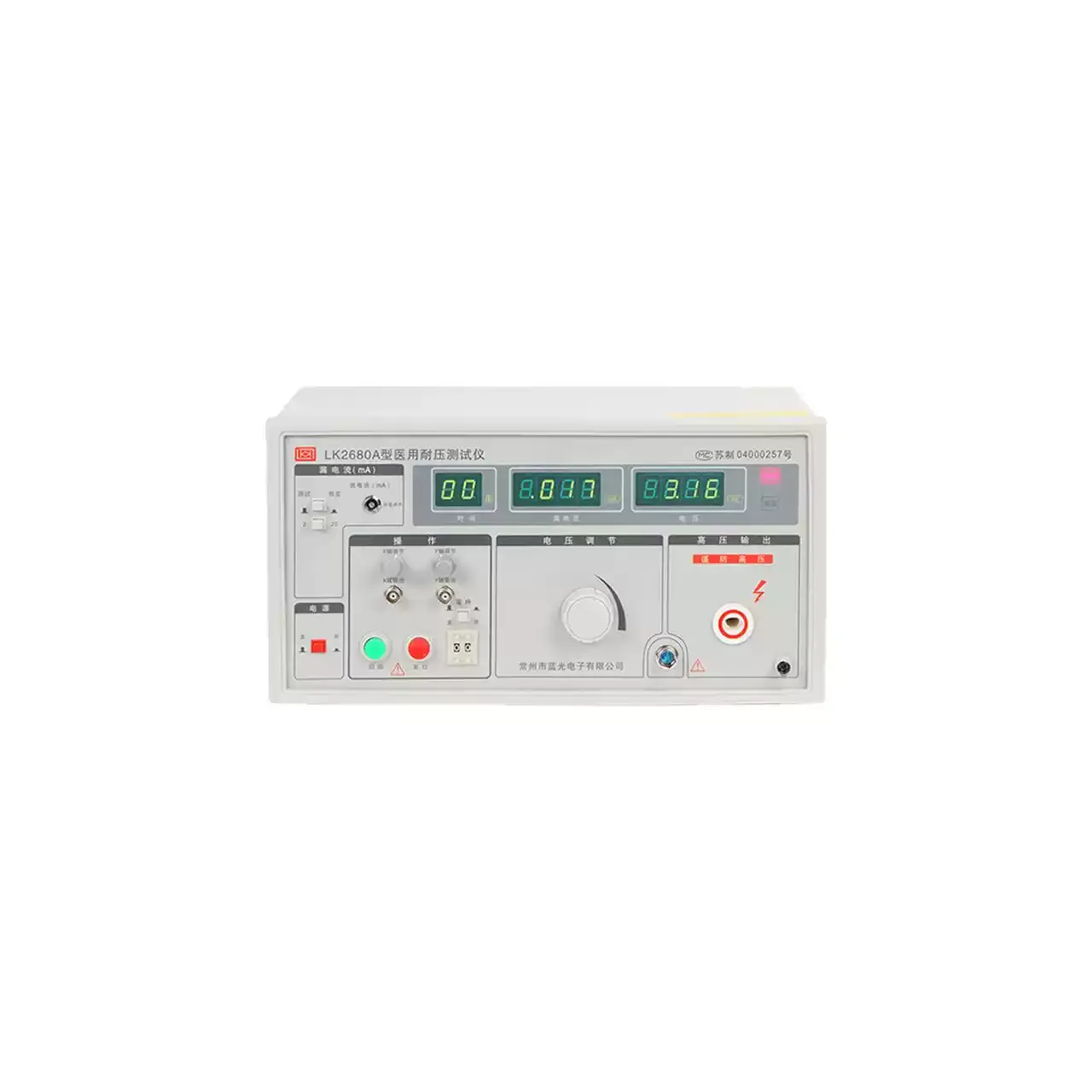
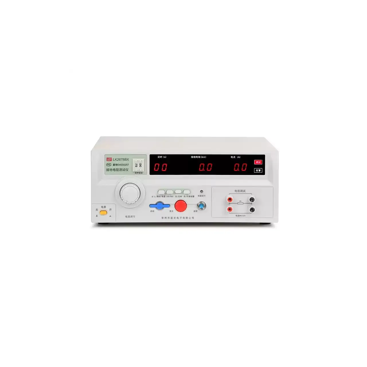
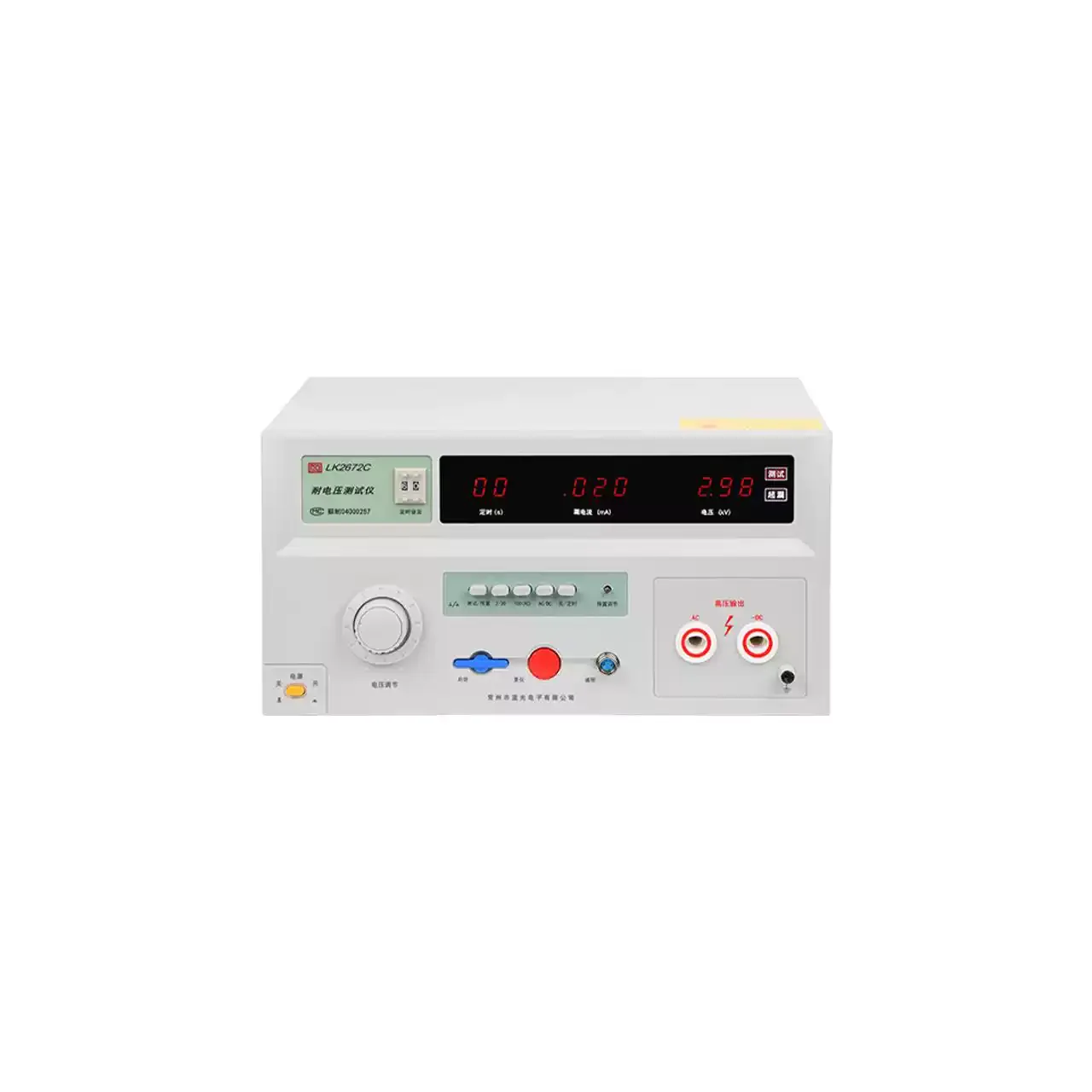
- Output voltage
- 0 to 250 V on the single-phase models; three-phase on LK2675S
- Transformer capacity
- 300 VA, 1000 VA or 2000 VA depending on model; LK2675E and LK2675S use an external variac
- Leakage range
- 0 to 2 mA or 0 to 20 mA, accuracy ±(5% + 5 counts)
- Measurement
- True-RMS AC/DC conversion, responding to direct, alternating, sine and composite waveforms
- Bandwidth
- Up to 1 MHz
- Test time
- 1 to 99 s, stopped automatically at the end of the interval
- Display
- Three digital displays for test voltage, leakage current and time
- Alarm
- Upper leakage limit continuously settable, with an over-leakage lamp and a long audible tone
- Supply polarity
- Automatic phase conversion
- Construction
- Integrated or split body, depending on the capacity of the equipment being tested
Leakage current is the smallest of the safety measurements and the easiest to get wrong, because the current being measured is often a fraction of a milliamp on a waveform that is not a sine wave. This range is built for that measurement, with a true-RMS converter and enough bandwidth to see what a switching supply actually leaks.
Product overview
Five models share the same measuring circuit and differ in where the test voltage comes from. Three contain their own adjustable transformer at 300 VA, 1000 VA or 2000 VA; two have no transformer and take their supply from an external variac, one single-phase and one three-phase.
All five measure 0 to 2 mA and 0 to 20 mA, run a 1 to 99 s test, and show voltage, leakage current and time on three separate displays. The front panel carries both a class I and a class II test outlet, because the two classes are measured on different paths.
How the leakage current tester works
The item under test is plugged into the instrument and energised from the adjustable supply. The instrument then measures the current that returns through the protective conductor, or through the class II input when the item has no earth connection, and displays it as a true RMS value.
The true-RMS conversion is what makes the reading meaningful. A heater draws a sinusoidal current and any averaging meter reads it correctly; a appliance with a phase-angle control or a switching supply draws a current with a high crest factor, and an averaging meter under-reads it. The converter responds to the actual heating value of the waveform, so the figure matches what the standard is protecting against.
The bandwidth of 1 MHz extends that to the high-frequency component a switching supply injects into the earth path. Without it, the reading would include the mains-frequency component and miss the part that causes the shock risk.
Automatic phase conversion reverses the live and neutral connection during the test, so the leakage at both supply polarities is covered without the operator re-plugging the item. The displayed test voltage is taken through a linear rectifier, so it follows the voltage at the load rather than the voltage at the source.
How to select the right leakage current tester
Start with the current the appliance draws, not with the leakage limit. The 300 VA model suits small appliances; 1000 VA and 2000 VA suit appliances with heating elements or motors. Above 2000 VA, or for a three-phase item, the external-variac models are the only option, and the variac becomes part of the bench.
The second question is the class of the appliance. Class I items are measured through the protective conductor, class II items through the class II input, and the front-panel switch has to be set accordingly. A bench that tests both needs the instrument in front of it rather than a fixed installation.
The third is the fixture. The PLC interface is optional, so a station that starts the test from a controller has to specify it. The test outlet type should also be confirmed against the plugs the production line actually uses.
Measurement limitations and selection considerations
The reading includes the current through the test socket, the leads and any fixture between the instrument and the appliance. Those paths have capacitance, and at 1 MHz a metre of lead can carry more current than the insulation being tested. The limit therefore has to be set with the fixture connected.
The instrument measures leakage, not insulation strength. An appliance that passes a leakage test can still fail a dielectric test, and one that passes both can still have a high-resistance protective bond. The three tests answer different questions and need different instruments.
The external-variac models depend on the variac for their output. A variac with a distorted output or a limited current rating changes the test conditions, so its specification becomes part of the measurement and has to be recorded alongside the instrument.
Finally, the leakage current of an appliance depends on its operating state. A heater that is switched off, a motor that is not running and a controller in standby each produce a different figure, and the standard usually names which state is to be measured. The instrument reports the current at the moment of the test; deciding which moment matters is the operator’s job.
Every value below is taken from source documentation. Where a parameter is not stated in the available material it is marked as information required rather than estimated.