- Withstand output
- 0 to 5 kV AC on LK2680A; 0 to 5 kV AC or DC on LK2680D
- Leakage ranges
- 0 to 2 mA or 20 mA, AC on LK2680A and LK2680CX; AC or DC on LK2680D
- Ground bond
- 5 to 32 A through 0 to 600 mΩ on LK2680B, open-circuit voltage 6 V or less
- Leakage test voltage
- 0 to 250 V on LK2680CX, with a 500 VA isolation transformer as standard
- Measurement bandwidth
- Up to 1 MHz on the leakage measurement, true-RMS AC/DC conversion
- Test time
- 1 to 99 s on every model
- Arc detection
- LK2680A and LK2680D, observed on an external oscilloscope
- Display
- Three displays showing voltage, current and time together
- Body
- 375 × 195 × 280 mm and 10 kg on LK2680A, LK2680D and LK2680CX; 350 × 135 × 280 mm and 8 kg on LK2680B
- Reference standard
- Designed to GB 9706.1-2020 and IEC 60601-1:2012 as stated in the material
A medical device is tested three ways before it leaves the bench: the insulation is stressed, the protective bond is measured, and the current it draws to earth is read. This range puts those three tests into four models that share a panel layout, so a laboratory can cover the whole sequence without buying three unrelated instruments.
Product overview
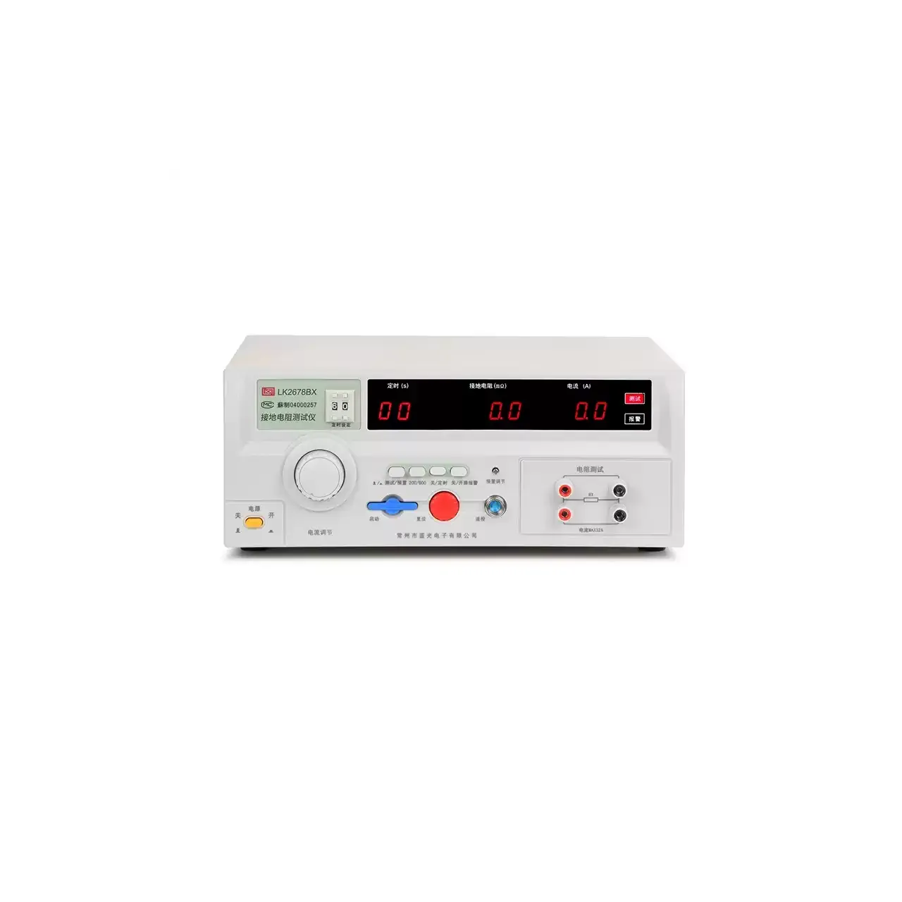
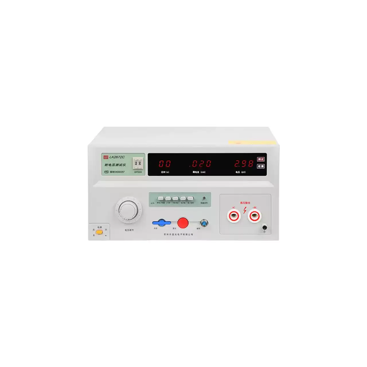
The range is organised by function rather than by power. LK2680A and LK2680D are dielectric testers, the second adding a direct output and both adding arc detection. LK2680B is a four-terminal ground bond tester. LK2680CX is a leakage current tester built around an isolation transformer.
The two dielectric models and the leakage model share a 375 mm wide, 10 kg body; the ground bond model is a smaller 8 kg case. All four run a 1 to 99 s test time and show voltage, current and time together, which is what a test record needs.
How the medical safety tester works
The dielectric test steps the mains up to as much as 5 kV and applies it between the device’s live parts and its accessible metalwork. The leakage current that flows is compared with a preset limit; a breakdown produces a sharp rise, the output is cut and the alarm sounds. On the two models with arc detection, the test voltage is also brought out to an oscilloscope, where a good insulation draws a closed Lissajous figure and a flashover disturbs its edge.
The ground bond test drives 5 to 32 A through the protective conductor and senses the voltage across it on a second pair of leads, so the resistance reported is the bond rather than the test lead. The open-circuit voltage is held at 6 V or less, which is what a protective conductor test requires.
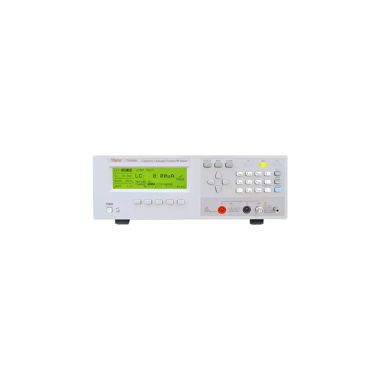
The leakage test applies the mains voltage through an isolation transformer and measures the current returning through the protective conductor or the applied part. The measurement is converted to a true RMS value, which matters because the current a switching supply leaks is not sinusoidal.
How to select the right medical safety tester
Start from the clause in the device standard, not from the model list. A dielectric test calls for LK2680A, or LK2680D where the standard also requires a direct test. A protective bond test calls for LK2680B. A leakage test calls for LK2680CX.
The second question is whether the bench needs arc detection. It is a diagnostic feature rather than a pass or fail one, and it earns its place where devices fail intermittently and the failure has to be located rather than simply recorded.
The third is the isolation capacity on the leakage model. The 500 VA standard unit covers small devices; a device with larger capacitance or a longer mains lead may need the 1 kVA version, and the suffix has to be written into the order because it changes the model code.
Measurement limitations and selection considerations
The leakage measurement includes the current through the test fixture and the leads. On a device with very low leakage that fixture current can be a large fraction of the reading, so the limit has to be set with the fixture connected and characterised, not from the device specification alone.
The dielectric test applies a 50 Hz sine wave. A standard written around a different waveform, or around a controlled ramp, is not reproduced by this output, and a test written for a direct voltage needs the DC model.
The ground bond measurement is a four-terminal one, which removes the lead but not the contact. Probe placement and clamp pressure can move a reading by more than the instrument error, so the same jig has to be used for readings to be comparable over time.
Finally, none of these instruments assesses the device’s performance. They establish that it is safe to touch, not that it measures, doses or displays correctly, and a device that fails a safety test still needs its functional checks after the fault is repaired.
Every value below is taken from source documentation. Where a parameter is not stated in the available material it is marked as information required rather than estimated.